Figure 5 figure 6, Air silencer modification – Banks Power Ford Motorhomes: (Gas ’93 - 98 7.5L Class-A) PowerPack System (Class-A, JD_OK chassis) For Use w_ 460 EFI Engine User Manual
Page 8
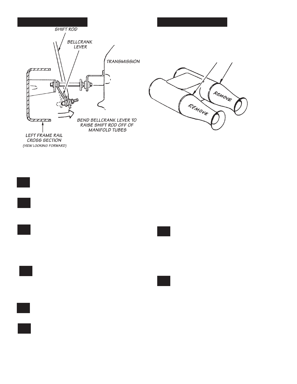
the removed section. Join the tube halves with
the 1-inch I.d. silicone hose and two no. 16 hose
clamps, provided. Make sure the tube ends are
pushed about one inch into the hose.
reinstall the catalytic converter and air
injection tubes on y-pipe flange. use new
gasket provided.
bolt the air injection tube to the tabs on the
right hand torquetube and y-pipe assembly
using four
5
⁄
16
-18 x 1” hex bolts, eight
5
⁄
16
sae washers
and four
5
⁄
16
-18 crimp-lock nuts. See Figure
4.
carefully remove the oxygen sensor from the
original head-pipe assembly and reinstall in
the banks y-pipe. re-connect the wiring. If wiring
will not reach sensor connector, trace wire loom
forward to locate excess wire bundle in engine
compartment. untie bundle and route wire as
required.
install the banks dynaflow muffler to the
catalytic converter. The stainless-steel
adapter supplied mounts between the converter
and muffler. note the alignment notch on the
adapter. use one 2
1
⁄
2
-inch and 3- inch u-clamp to
complete the assembly. See Figure
1.
attach the existing front muffler hanger
bracket to the 3-inch u-clamp to support the
front of the muffler.
Install the Monster tailpipe assembly. use
existing hangers in vehicle to support tailpipe.
the following combinations of tailpipe components
should be used to cover the wheelbases listed. do
not snug u-clamps until you are satisfied with pipe
alignment.
A. if the coach is a 178” wheelbase model, install
the tailpipe bend directly into the muffler outlet.
B. if the coach is a 208” wheelbase model, install
a 32
1
⁄
4
” intermediate pipe between the muffler and
the tailpipe. If the wheelbase is between 178” and
208”, shorten the intermediate pipe as necessary.
C. if the coach is a 228” wheelbase model, install
a 52
1
⁄
4
” intermediate pipe between the muffler and
tailpipe. If the wheelbase is between 228” and
208”, shorten the intermediate pipe as necessary.
an additional u-clamp is provided with this pipe for
hanging.
install the chrome tip and chrome tailpipe
heat shield on the tailpipe as shown in
Figure 1. tip may be slid in or out on the tailpipe to
match the body width.
NOTE: If possible, leave tailpipe within 2” of end
of chrome tip inside the tip. This will protect the
chrome from changing color from high exhaust
heat. Shorten tailpipe if required.
cut the 6 x 14” foil heat blanket, provided,
lengthwise to form two 3” x 14” strips. Wrap
one strip lengthwise around each brakeline tube
where the brakeline tube is closest to the exhaust
manifold tubing on each side of the engine. secure
foil strips with wire ties provided. dO nOT wrap the
foil heat blanket material around the TorqueTubes.
the heat blanket will not survive if it is in direct
contact with the manifold tubing.
NOTE: Brake lines may be bent somewhat to
provide additional clearance to the TorqueTubes.
Be careful not to kink brake lines. Vapor recovery
line on right side of engine may also need to be
bent back if it is within 1
1
⁄
2
” of TorqueTubes.
29.
28.
27.
26.
25.
24.
23.
22.
8
figure 5
figure 6
cut off tapered
portion here
air silencer modification
p.n. 96347