Installation procedure – Banks Power Ford Trucks: (Gas ’87 - 97 7.5L EFI) Powertrain- TransCommand For E40D_4R100 transmissions User Manual
Page 7
7
p.n. 96370
insTallaTion ProCedure
Raise the front of vehicle on ramps, jack stands,
or a lift if available. do noT work under
anY VehiCle suPPorTed onlY bY a JaCk!
Locate the body reinforcement stringer running
parallel to and outside of the frame rail under
the passenger side of the vehicle. now, locate the
crossmember which is supporting the rear of the
transmission. The Transcommand
™
will be mounted to
the stringer just slightly forward of the crossmember.
See Figure
1.
do noT mount the TransCommand
™
to the frame rail, as it may become hot.
using the Transcommand
™
mounting bracket
as a template, mark drilling locations on the
stringer. drill two mounting holes using a
9
⁄
32
” drill.
NOTE: On some vehicles it may be necessary to mount
the TransCommand
™
to the body next to the frame
rail. In this case, mark drilling locations using the
TransCommand
™
bracket as a template and drill two
mounting holes using a
3
⁄
16
” drill.
using two
1
⁄
4
–28 x
5
⁄
8
” bolts and two
1
⁄
4
–28 nylock
nuts, mount the Transcommand
™
to the body
reinforcement stringer as shown in Figure
1.
NOTE: On vehicles where the TransCommand will mount to
the body next to the frame rail, mount the TransCommand
using two
1
⁄
4
” dia. x
5
⁄
8
” sheet metal screws provided.
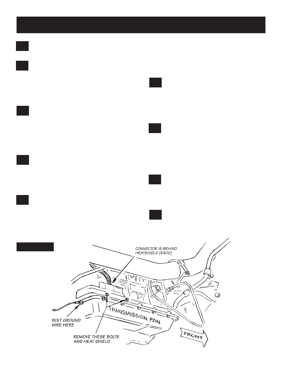
Identify the factory transmission control wiring
harness on the right (passenger) side of the
transmission. See Figure
2.
disconnect this wiring
harness by pressing on the retaining tab on the outside
of the connector near the top and pulling the connector
upward.
NOTE: On vehicles equipped with an E40D, this plug is
located behind the small metal shield. Using an 8mm
wrench, unbolt this shield to reveal the plug. On vehicles
equipped with a 4R100, it may be necessary to unbolt
the exhaust heat shielding and slide it out of the way to
access the plug. (There is no small metal shield.)
using a slim pair of needle-nose pliers, or a
hemostat clamp, remove the red plastic wedge
from between the two rows of pin sockets in the
transmission control wiring harness connector. On
1995 and later models, the pins are held in place with
a red retainer. Remove the retainer by placing a small
screwdriver tip between the connector shell and the
retainer and prying the retainer out. See Figure
3.
using Figure
3
as a guide, identify the pin
locations in the transmission control wiring
connector.
IMPORTANT: Make a diagram showing the wire
colors of pins 1, 11, and 12. Write them down on
Figure 3. These colors vary with the vehicle year
and must be hooked to the proper connections in
later steps. nOTe: If wire color of pins 1 & 12 are both
red, mark/tape the pin-12 wire, for later identification.
Reach in through the front of the connector
with a small screwdriver or sharp scribe; gently
move the locking tang away from pin no. 1 and remove
the wire and pin socket from the back side of the
connector body. Repeat for pin socket no. 11. Repeat
for pin socket no. 12.
using Figures
3
and
4
as a guide, insert three
female socket/wire ends from the banks
Transcommand
™
harness into the factory transmission
control wiring connector body as follows:
9.
8.
7.
6.
5.
4.
3.
2.
1.
FIgURE 2