General installation practices, Installation instructions – Banks Power Ford Motorhomes: (Gas ’93 - 98 7.5L Class-A) Power Systems- Stinger System (Class-A, JD-OK chassis) '93-98 For Use w_ 460 EFI Engine User Manual
Page 3
general installation practices
for ease of installation and trouble-free operation
of your Banks stinger, please read this entire
8-page owner’s manual before starting any work.
(If any pages are missing from this package, please
call gale banks engineering immediately for a
replacement). become thoroughly familiar with all
components and phases of the installation before
starting any work.
inspect all components supplied for any foreign
material that may have entered during shipping
and handling.
warning: motorhomes are very heavy. whatever
methods are used to elevate the vehicle must
be of sufficient capacity for the vehicle weight
involved. neVer work under any vehicle supported
only by a jack of any kind. do not use concrete
blocks or other masonry items that may collapse
under the vehicle weight.
pay particular attention to the routing of any wires.
Keep them away from exhaust heat, moving parts
and sharp edges that may cause cuts or other
damage. route or tie wires away from critical
areas as required. keep all wires a minimum of 6
inches from hot exhaust parts, 8 inches or more is
recommended whenever possible.
right-hand and left-hand designations refer to
the driver’s right or left, as seated in the vehicle,
(i.e.: right-hand refers to the passenger side of
the vehicle, unless noted otherwise.
the banks motorhome stinger is designed to
fit class a 460 ford/oshkosh and john deere
engine/chassis combinations. because of different
equipment layouts used by various coach builders,
some accessories and components may have
to be relocated to accommodate the air intake
components of the banks stinger.
Notification
The Banks Ram-Air Filter comes pre-
oiled and no oiling is necessary for initial
installation. Service the filter as specified
in the Cleaning and Oiling the Banks Ram-
Air Filter Section of this manual.
3
p.n. 96376
installation instructions
If a heavy duty hoist is available, raise the
vehicle and remove the front wheels for easier
access. If the rear wheels remain on the ground,
block the rear wheels.
starting from the rear of the vehicle and
working forward, remove the tail pipe
assembly from the vehicle. leave exhaust pipe
hangers in place on the chassis. note: some joints
may require the heat from a torch to loosen them for
disassembly.
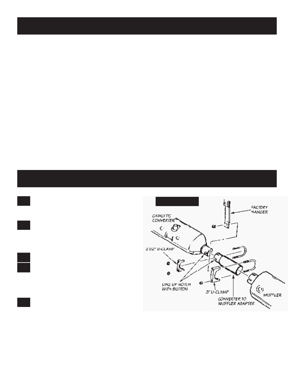
remove muffler from catalytic converter.
install banks dynaflow™ muffler to the
catalytic converter. the stainless steel adapter
supplied, mounts between the converter and muffler.
note the alignment notch on the adapter. use one
2
1
⁄
2
” and 3” u-clamp to complete the assembly. See
Figure
1.
attach the existing front muffler hanger
bracket to the 3-inch u-clamp to support the
front of the muffler.
install the monster™ exhaust tailpipe assembly.
use existing hangers in vehicle to support tailpipe.
the following combinations of tailpipe components
should be used to cover the wheelbases listed. do
not snug u-clamps until you are satisfied with pipe
alignment.
A. if the coach is a 178” wheelbase model, install
the tailpipe bend directly into the muffler outlet.
B. if the coach is a 208” wheelbase model, install a
32
1
⁄
4
” intermediate pipe between the muffler and the
tailpipe. if the wheelbase is between
1
⁄
8
” and 208”,
shorten the intermediate pipe as necessary.
C. if the coach is a 228” wheelbase model, install
a 52
1
⁄
4
” intermediate pipe between the muffler and
tailpipe. If the wheelbase is between 228” and 208”,
shorten the intermediate pipe as necessary. an
1.
2.
3.
4.
5.
figure 1