Installation instructions, Figure 1 – Banks Power Ford Motorhomes: (Gas ’93 - 98 7.5L Class-A) PowerPack system (Class-A, Carb, JD-OK Chassis) For use w_ 460 carbureted engine User Manual
Page 5
installation instructions
remove the “dog house” cover from the
engine for acess.
If a heavy duty hoist is available, raise the
vehicle and remove the front wheels for
easier access. If the rear wheels remain on the
ground, block the rear whels.
disconnect all cables from the batterys).
starting from the rear of the vehicle and
working forward, remove the exhaust
system from the vehicle. leave exhaust pipe
hangers in place on the chasis.
disconnect the rubber hoses from the air
injection tubing on the exhaust manifolds.
remove the exhaust manifolds from the engine.
(see notes on bolt removal)
note: Some models do not use manifold air injec-
tion. If not equipped with manifold air injection,
go to step 7.
remove the air injection tube assemblies
from the exhaust manifolds. you may need
to use heat and/or penetrating oil on the tubing
nuts. use a flare-nut wrench to avoid rounding of
the corners of the tubing nuts.
disconnect the main positive power cable
(large red cable) from the stud on the starter
motor.
re-route the main power cable to the
starter motor by feeding the cable between
the side engine mount and the oil pan. cut the
plastic cable ties on the forward part of the cable
bundle as required to provide slack as needed for
the new cable routing. re-connect the cable to
the starter motor.
inspect the cylinder head exhaust flange
surfaces. remove any loose carbon, rust,
old gasket material, etc. as required to provide a
clean, flat manifold mounting surface.
put the transmission in low gear (make sure
wheels are blocked to prevent rolling). bolt
the banks exhaust manifolds to the cylinder heads.
use the new gasket/heat shields provided between
the cylinder heads and manifolds. attach the new
manifolds with
3
⁄
8
–16 x 1 inch 12-point bolts. use
anti-sieze compound on the threads.
re-install the air injection tubing assemblies
to the new exhaust manifolds. hook up
the hoses to the air injection tubing assemblies.
(if engine is not equipped with a manifold air
injection system, install eight plugs, provided, in
the new exhaust manifods.)
re-connect the hot air tube from the air
cleaner to the heat stove pipe on the
exhaust maniold.
check that the re-routed cable to the starter
motor has at least 3 inches of clearance to
any part of the exhaust manifold tubing. also
check that the cable will not rub on any sharp
edges that could cut through the insulation and
cause a short. reposition or tie the cable in place
to correct any of these conditons.
starting from the exhaust manifold
outlets, install the new exhaust piping and
muffler (see Figure
1
). the two floating exhaust
flanges must be slid onto the head pipes prior to
installation. note the new position of the spring at
the forward muffler hanger. universal hangers and
clamps are provided for your use if necesary.
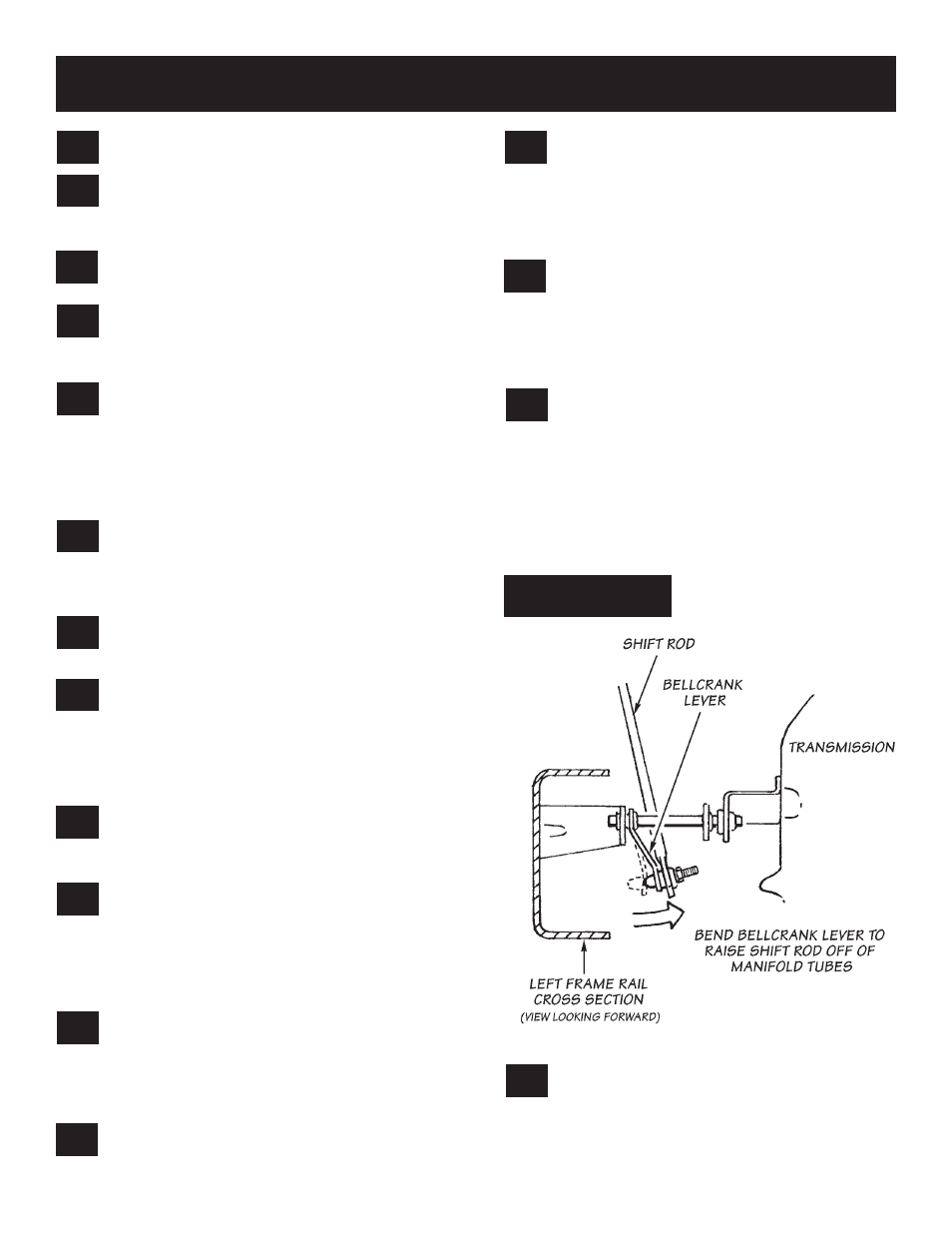
To prevent the transmission shift rod from
rattling against the exhaust manifold tubes,
bend the shift rod bellcrank lever as required to
provide clearance between the tubes and the
rod. run the shift lever in the vehicle through all
gear positions, and check that the shift rod clears
the exhaust tubes. If possible, try to maintain
1
⁄
4
inch or more clearance to prevent contact during
engine rock-over. See Figue
2
.
bolt the heat shield bracket to the left side
heat shield using two
5
⁄
16
–18 x
3
⁄
4
hex bolts,
5
⁄
16
I.d. x
9
⁄
16
o.d. washers, and
5
⁄
16
–18 nylock nuts
(see Figure
3
).
16.
15.
14.
13.
12.
11.
10.
9.
8.
7.
6.
5.
4.
3.
2.
1.
5
p.n. 96345
fIgure 1