Banks Power Ford Trucks: (Diesel ’03 - 07 6.0L Power Stroke) Power Systems- PowerPack & Stinger '03-07 Compatible w_ Optional Banks iQ User Manual
Page 32
32
96824 v.3.0
Not needed if Banks iQ will be
installed. Please proceed to Section
7.
Caution: Do not use excessive
force when working on plastic
parts. Permanent damage to the
part might result
For 2003-04 model year vehicles,
follow the selector switch
installation procedure Step 1.
For 2005-07 model year vehicles,
skip to Step 7.
1.
Remove the lower driver side
interior panel that allows access to the
fuse box.
2.
Remove the stereo using Ford
stereo removal tools as shown in
Figure 46. These are readily available
at automotive supply stores.
3.
Remove two (2) bolts that reside
above the stereo. These are accessible
once the stereo has been removed.
4.
Detach the dash. At this point
the dash is held in place entirely by
removable fasteners. Disconnect all
electrical connections on the back of
the dash once it has been detached.
5.
Remove the dash from the vehicle.
6.
cut out the Template 3 in Page
41 of this manual and tape to the
backside of the dash panel as shown
in Figure 47 for 2003-04 model year.
The template will be used as a guide
for drilling the holes to locate the Six-
Gun selector switch.
For 2003-04 model year vehicles,
skip to Step 9 to finish the selector
switch installation procedure.
7.
2005-07 Automatic Transmission
vehicles: Set the vehicle’s parking
brake. Insert the key and turn the
vehicle on without starting it. Pull the
shift lever down into first gear to allow
clearance for dash panel removal.
All 2005-07 vehicles: Pull the plastic
trim surrounding the instrument panel
and radio / climate controls towards
you until it releases from the main
dashboard — it is attached by a series
of spring clips around its perimeter.
Disconnect all electrical connectors
from the back of the dash trim and
remove it from the vehicle.
8.
cut out the Template 4 in Page
41 of this manual and tape it to the
front of the dash panel as show in
Figure 48. The template will be used
as a guide for drilling holes to locate
the power level selector switch.
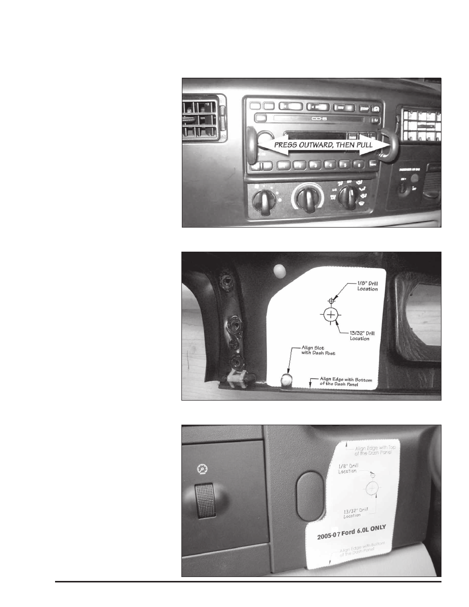
Figure 46 Removal of the stereo (2003-04 model year vehicles only)
Section 6
INSTALLATION OF THE POWER LEVEL SELECTOR SWITCH
Figure 47: Template taped to back of dash on 2003-04 model year vehicle, ready
to be drilled.
2003-04 model year vehicles only
Figure 48 Template taped to front of dash on 2005-07 model year vehicle,
ready to be drilled.
2005-07 model year vehicles only