Banks Power Ford Trucks: (Diesel ’03 - 07 6.0L Power Stroke) Exhaust- Monster Exhaust, Single Passenger side exit, F-250_F-350 '03-07 Pickup Trucks and Excursions User Manual
Page 8
6.
The catalytic converter inlet will
need to be trimmed to accommodate
the Banks exhaust system. Be careful
not to trim an excessive amount of
tubing. Be sure to wear proper
safety equipment.
IMPORTANT: Diesel catalysts
may become plugged with soot
which can restrict exhaust flow,
impeding performance. Inspect the
converter by shining a powerful
flashlight into the inlet. Observe
the light through the other end of
the converter. The full circle of the
flashlight should be visible without
any blockage in the gridwork of
the catalyst.
If excessive soot is observed, the
catalyst may need to be cleaned.
TAKE PRECAUTIONS to avoid lowing
soot toward the work area or
where it could be inhaled. ALWAYS
use breathing protection. Also
inspect the catalyst for damage
(i.e. chips, bent corners, etc.) to
the gridwork. If your catalytic
converter is damaged, it may
be covered under your vehicle’s
emissions warranty.
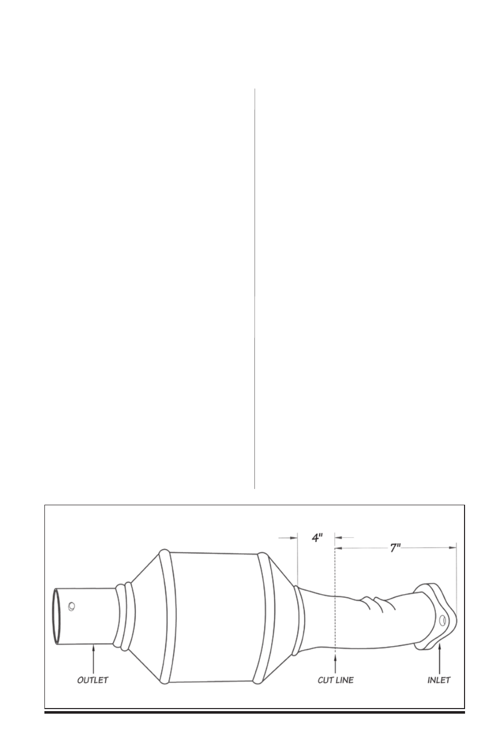
A) With the catalytic converter
removed from the vehicle and the
headpipe removed from the converter,
measure approximately 4” from the
weld and mark the location (this
location should be before any bend,
about 7” rear of the inlet flange). Using
a reciprocating saw or equivalent,
vertically cut and remove 7” from the
converter outlet tubing (see Figure 2).
B) Install the supplied Banks front
intermediate pipe onto the previously
installed Banks T.O.P. Loosely install
a supplied 4” exhaust clamp onto
the forward end of the front
intermediate pipe.
c) Install the supplied 3
1
⁄
2
” clamp onto
the outlet of the front intermediate pipe.
Place the trimmed catalytic converter
onto the previously installed front
intermediate pipe. Loosely snug the
clamp onto the catalytic converter inlet.
7.
Place a supplied 3
1
⁄
2
” clamp
onto the front of the supplied rear
intermediate pipe.
Note: Review the Parts List Table on
page 11 to verify the rear intermediate
pipe P/N.
Figure 2
8
94440 v.13.0