Velleman LPTT1202 User Manual
Page 3
LPTT1202 GB
3
10. EXT. POWER
: for operation test only
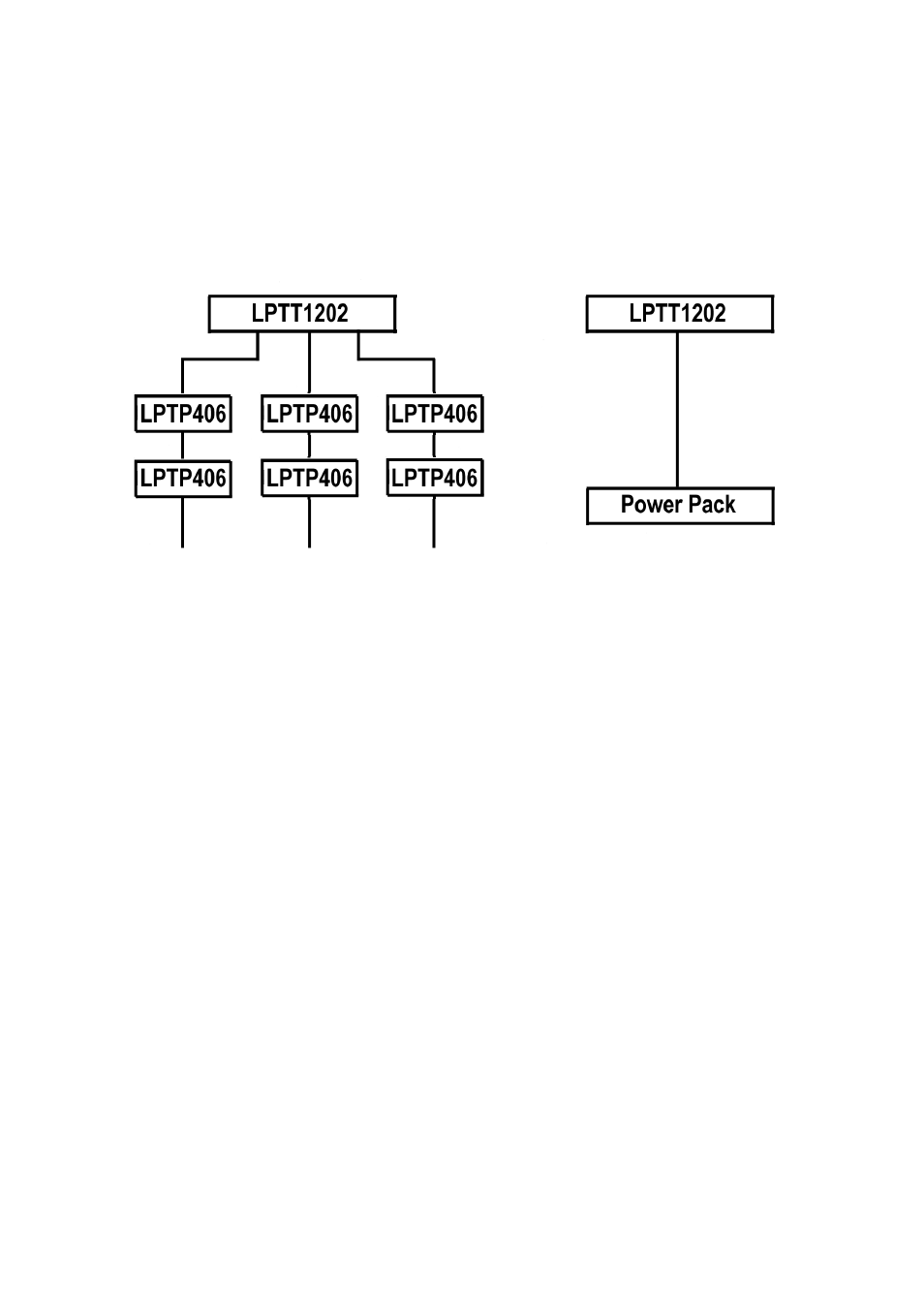
11. SIGNAL OUT (2 x 6 CHs) : 8-pin DIN sockets for connection to a LPTP406 (*)
12. SIGNAL OUT (3 x 4 CHs) : 8-pin DIN sockets for connection to LPTP406 (*)
13. SIGNAL OUT (1 x 12 CHs) : 25-pin SUB-D connector for connection to a power pack
(*) The LPTP406 is a 4-channel patchable power pack, 10A/channel
CONNECTIONS (see also figure above)
6. Cleaning and Maintenance
1. All screws should be tightened and free of corrosion.
2. The housing, mounting supports and connections should not be modified or tampered with
e.g. do not drill extra holes in mounting supports, do not change the location of the
connections, …
3. The electric power supply cables should be undamaged. Have this device installed by a
qualified technician.
7. Caution
•
Disconnect the device from the mains prior to maintenance.
•
Use a moist cloth to clean the device and avoid the use of alcohol or solvents for cleaning
purposes.
•
Replace a blown fuse with an identical one.
•
Spare parts should be ordered with your local dealer.
8. Technical Specifications
Power Supply
+20Vdc through power pack
Number of Channels
12
Signal Output
ON DC +10V; OFF DC +0V
Dimensions
482 x 75.5 x 88mm
Weight 1.3kg
The information in this manual is subject to change without prior notice.