Cleaning and maintenance – Velleman VDPL300QF2 User Manual
Page 6
VDPL300QF2
V. 03 – 22/06/2012
6
©Velleman nv
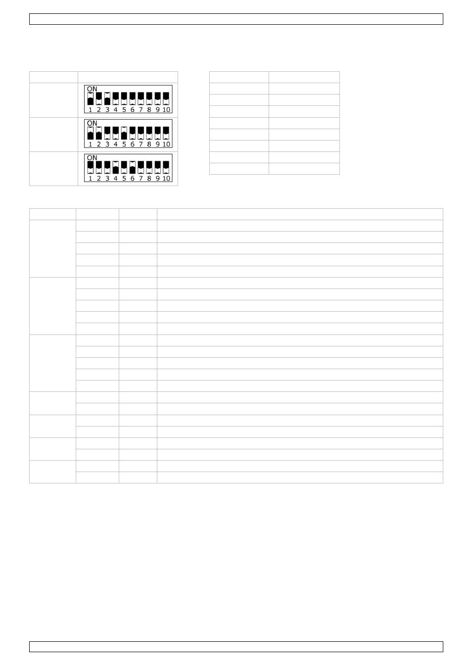
To set the device to work with a DMX controller:
1. On the back panel [5], set DIP switches 9 and 10 to OFF.
2. Use DIP switches 1 – 8 to specify the DMX address:
address DIP
switches switch represents
5
1 1
2 2
3 4
19
4 8
5 16
6 32
40
7 64
8 128
DMX channel values
Channel From To Function
1
0 6
Off
7
66
Group 1 red lights on
67
129
Group 2 red lights on
130
192
Group 3 red lights on
193
255
All red lights on
2
0 6
Off
7
66
Group 1 green lights on
67
129
Group 2 green lights on
130
192
Group 3 green lights on
193
255
All green lights on
3
0 6
Off
7
66
Group 1 blue lights on
67
129
Group 2 blue lights on
130
192
Group 3 blue lights on
193
255
All blue lights on
4
0 6
Off
7
255
All white lights on
5
0 30
Off
31
255
Built-in program (speed increases according to channel settings)
6
0 30
Automatic
31 255
Built-in
program
7
0
30
Strobe effect off
31
255
Strobe effect (speed increases according to channel settings)
Notes
•
CH1 to CH4 can work together with CH5; the values of CH5 must be set between 0 and 30.
•
When using CH 6, the values of CH5 must be set between 31 and 255.
•
You can use CH1 to CH6 together with CH7 for strobe effects.
•
Channel 7 (strobe) only works if other channels (CH 1 to CH 6) are active.
8.
Cleaning and maintenance
•
All screws should be tightened and free of corrosion.
•
The housing, visible parts, mounting supports and the installation location (e.g. ceiling, suspension,
trussing) should not be deformed, modified or tampered with; e.g. do not drill extra holes in mounting
supports, do not change the location of the connections…
•
Moving mechanic parts must not show any signs of wear and tear.