Velleman VDP1001GLD7 User Manual
Page 5
VDP1001GLD7
VELLEMAN
5
b.
Back
6.
Cooling fan intake
7.
DIP switches: allow you to assign your projector a DMX address as well as select operation modes
8.
Remote interlock connector: DE-9 connector to the remote interlock which stops the laser beam emission once
the connection loop has been opened
9.
a. Signal in: standard DMX512 cable connection to a DMX controller or connection used to run projector in a
master-slave chain
b. Signal out: standard DMX512 cable connection to a DMX controller or connection used to run projector in a
master-slave chain
10.
Cooling fan outlet
11.
Power cord input storing the internal fuse
12.
Power switch: turn the unit on or off. Make sure the unit is turned off before connecting to the mains
13.
Locking system: when locked, the unit will stop emitting the laser beam but will remain active
14.
Sound sensitivity control for use in sound mode
5. Operation
Your VDP1001GLD7is designed to operate using the DMX512 protocol which allows you to control the projector
using a DMX512 controller. However, a profile must be created for some controllers. By following the instructions
below, you will be able to ensure a safe use of your projector.
Your projector can be operated using three modes: DMX512 mode, master-slave mode or stand alone operation.
Additionally, the device can be remotely operated from a DMX512 remote controller. It features over 300 effects
triggered by the above modes.
a.
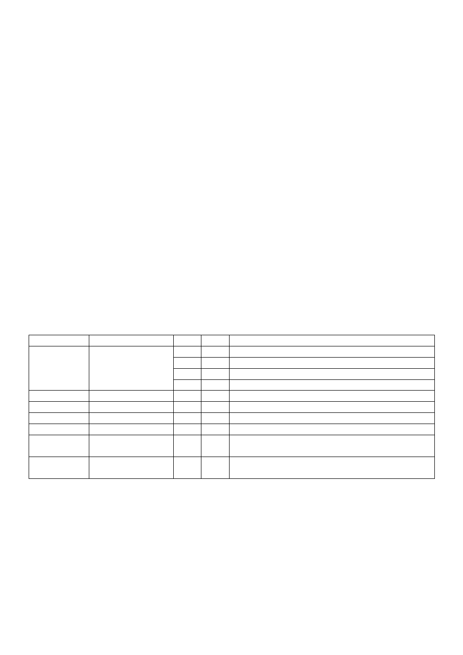
Detailed DMX Values per Channel
Channel
Function
From
To
Description
1
10
Laser off, laser and scanner stop working
11
120 Dynamic patterns
121
250 Static patterns
Channel 1
MODE
251
255 Sound active mode
Channel 2
PATTERN
0
255 Choose your static or dynamic pattern
Channel 3
POSITION X
0
255 Adjust position X
Channel 4
POSITION Y
0
255 Adjust position Y
Channel 5
SCANNING SPEED
0
255 0 = fast, 255 = slow
Channel 6
DYNAMIC PATTERN
PLAYING SPEED
0
255 0 = fast, 255 = slow
Channel 7
STATIC PATTERN
SIZE
0
255 0 = small, 255 = large
b.
DMX512 Connection
Connect the provided XLR cable to the female 3-pin XLR output of your controller and the other side to the male 3-
pin XLR input of the VDP1001GLD7. Multiple VDP1001GLD7s can be linked through serial linking. The linking cable
should be a two-core screened cable with XLR input and output connectors.