Velleman VDPL110GL User Manual
Page 5
10.01.20
res
in t
c) Gene
•
Ma
coo
•
Hav
•
Co
•
The
7. Op
Refer to t
•
Relea
•
Inser
•
Rese
•
Inser
main
•
The V
mod
Automa
•
Set
•
Set
•
Set
•
Set
•
Set
No
Slave m
•
Co
•
Set
DMX co
•
Set
•
All
sig
the
ind
•
Wh
par
sim
num
•
In
(CH
•
Use
•
Ref
Ch
011
sistor between p
the chain.
eral
ke sure there is
oling.
ve a qualified e
nnect the devic
e installation ha
eration
the illustrations
ase the two bolt
rt a 29mm gobo
at the gobo hol
rt the power plu
s.
VDPL110GLcan
e.
atic mode
t DIP switch 9 [
t DIP switch 1 [
t DIP switch 2 [
t DIP switch 3 [
t DIP switch 4 [
otes:
•
When DIP
•
only the h
mode
nnect multiple V
t DIP switches 1
ontrolled mo
t DIP switch 10
DMX-controlled
nals. This digita
e DMX controller
dividual address
hen all devices h
rticular channel
multaneously. If
mber. Changing
case of the 2-ch
H1~2), the seco
e the DIP switch
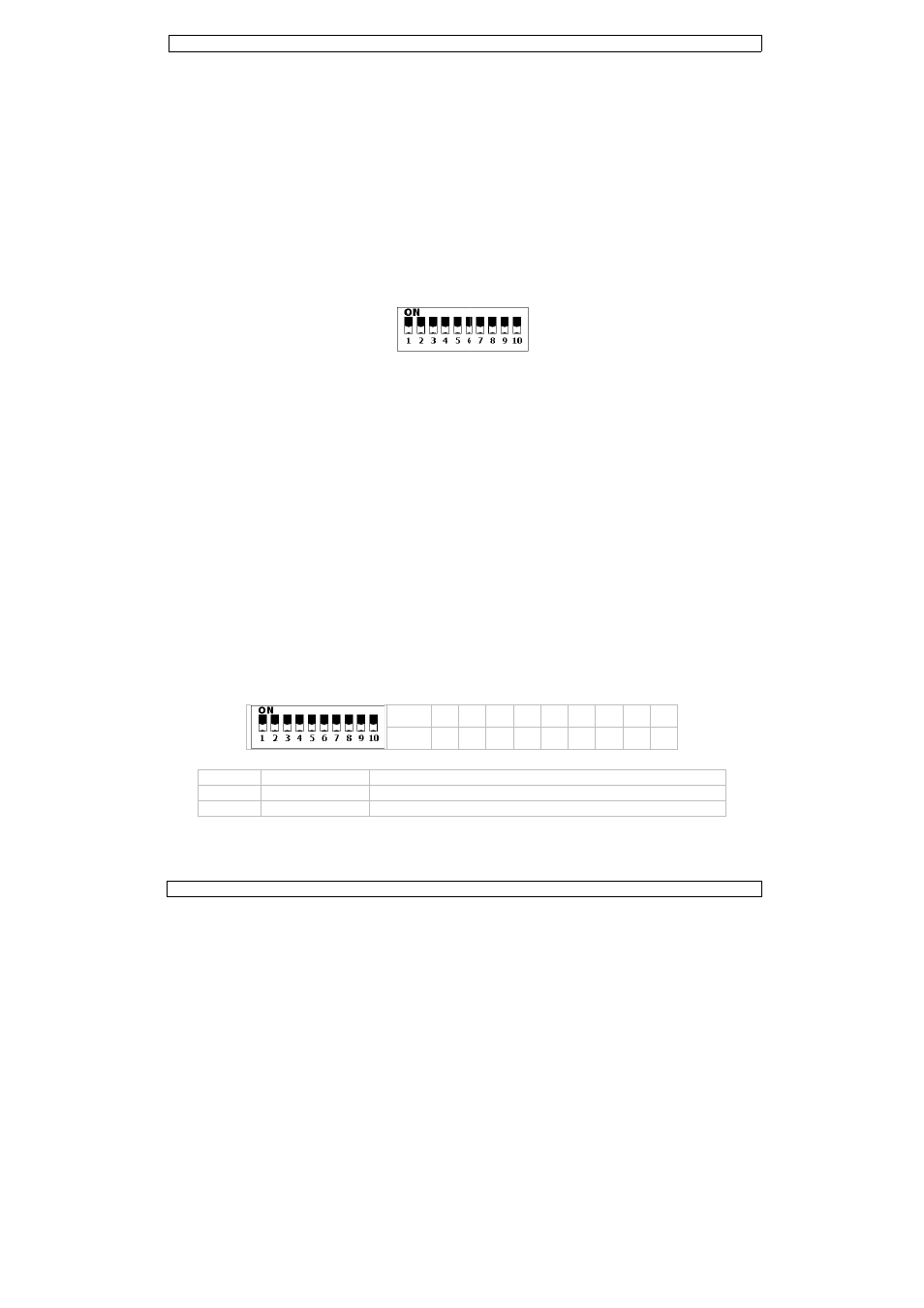
fer to the table
hannel DMX-5
CH1
000
CH2
000
pins 2 and 3, wh
s no flammable
lectrician carry
e to the mains w
as to be approve
s on page 2 of th
ts and slide the
o (included).
der [8] and sec
ug into the powe
n operate in thr
[1] to ON and D
[1] to ON to rot
[1] to ON to rot
[1] to ON to rot
[1] to ON to fre
switches 1, 2,
ighest DIP switc
VDPL110GL’s a
1 and 10 [1] to
de
[1] to the ON
d devices need a
al start address
r. The same sta
can be set for
have the same a
. In other words
you set individ
g the settings of
hannel VDPL11
ond unit to 3 (1
hes [1] to set t
below for an ov
512 value Fu
0 ~ 255
dim
0 ~ 255
gob
VDPL11
5
hich is then plug
material within
out the electric
with the power
ed by an expert
his manual.
gobo holder [8
cure it with the
er input [5]. Ins
ree modes: auto
DIP switch 10 [1
tate the gobo at
tate the gobo at
tate the gobo at
eze the gobo (L
3 and 4 are set
ch takes effect
as described in
ON to enable s
position to enab
a digital start ad
is the channel n
arting address ca
every device.
address, all the
s: changing the
ual addresses, e
f one channel w
10GL, you will h
+ 2) (CH3~4),
he appropriate
switch 1
2
value 1
2
verview of the c
nction
mmer: 0% ~ 10
bo rotating spee
10GL
gged into the XL
a 50cm radius
al connection.
plug. Don’t con
t before the dev
8] out of the hou
two bolts.
sert the other e
omatic mode,
1] to OFF to ena
t slowest speed
t average speed
t fastest speed (
LED on).
to OFF, the LED
§6.b.
slave mode.
ble DMX control
ddress so that t
number from w
an be used for a
units will “listen
settings of one
each device will
will only affect th
have to set the s
the third to 5 (
DMX address.
2 3 4 5
2 4 8 1
ontrol signals p
00%
ed: 0 ~ 100%
LR output socke
of the device an
nect it to a dim
vice is taken into
using.
end of the powe
slave mode or
able automatic
(LED on).
d (LED on).
(LED on).
D will be off.
led mode.
he correct devic
hich the device
a whole group o
n” to the contro
e channel will af
“listen” to a se
he device in que
start address of
(3 + 2) (CH5~6
5 6 7 8
6 32 64 12
er channel.
©Vellem
et of the last dev
nd there is suffi
ming pack.
o service.
r cable into the
r DMX controll
mode.
ce responds to t
starts to “listen
of devices or an
ol signal on one
ffect all devices
eparate channel
estion.
f the first unit to
6), and so on.
8 9
28 256
man nv
vice
cient
ed
the
n” to
o 1