Installation – Velleman PEM10D2 User Manual
Page 6
PEM10D 2
V. 02 – 27/11/2013
6
©Velleman nv
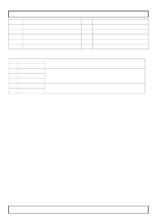
A
hood
G
terminals
B
mounting bracket
H
cover
C
transmitter/receiver lens
I
gland
D
alignment LED
J
mounting bolt
E
tamper switch
K
wall cable hole
F
vertical alignment bolt
L
screw (4x)
Term inals (image page 3)
1
input voltage input voltage 12 ~ 250V AC or DC (no polarity)
2
input voltage
3
NC
output contacts
normally closed between 3 and 5
Normally open between 4 and 5
4
NO
5
COM
6
TP1
tamper contact: open when tamper switch is
pressed (cover is closed)
7
TP2
6. Installation
•
Determine a location for the system. Avoid direct sunlight on the
transmitter/receiver lens [C] and note that the maximum distance
to the reflector is 10m. Make sure to point towards a flat surface
to which the reflector can easily be mounted. Also keep in mind
that when mounting the system too low, an alarm might
accidentally be triggered by small animals e.g. pets.
•
Remove the mounting bracket [B] from the housing by releasing
the two mounting bolts [J].
•
Use the mounting bracket [B] as a template to determine the
position of the mounting holes and mount the bracket with 2
screws.
•
When the cable needs to go through a wall cut away the wall cable
hole [K]; hang the housing over the mounting bracket and mark
the location of the cable hole. Remove the housing and drill the
hole and provide the necessary cabling. Mount the included rubber
seal in the wall cable hole.
•
When the cable runs on top of the wall cut away the hole at the
bottom of the housing and mount the cable gland [I] in the
opening (do not tighten the nut that covers the conical part).
Provide the necessary cabling.