Velleman VDPL110CC User Manual
Page 5
17.01.20
c) Gene
•
Ma
coo
•
Hav
•
Co
gro
or
•
The
•
To
des
7. Op
Refer to t
•
The V
man
Sound
•
Set
•
Set
Automa
•
Set
•
Set
Slave m
•
Co
•
Set
•
Set
Manual
•
Set
Note
DMX co
•
Set
•
All
sig
the
ind
•
Wh
par
sim
num
•
In
(CH
•
Use
•
Ref
011
eral
ke sure there is
oling.
ve a qualified e
nnect the devic
ounded switched
dimmer channe
e installation ha
adjust the focu
sired focus and
eration
the illustrations
VDPL110CC
ca
ual mode or D
controlled m
t DIP switch 10
t the microphon
atic mode
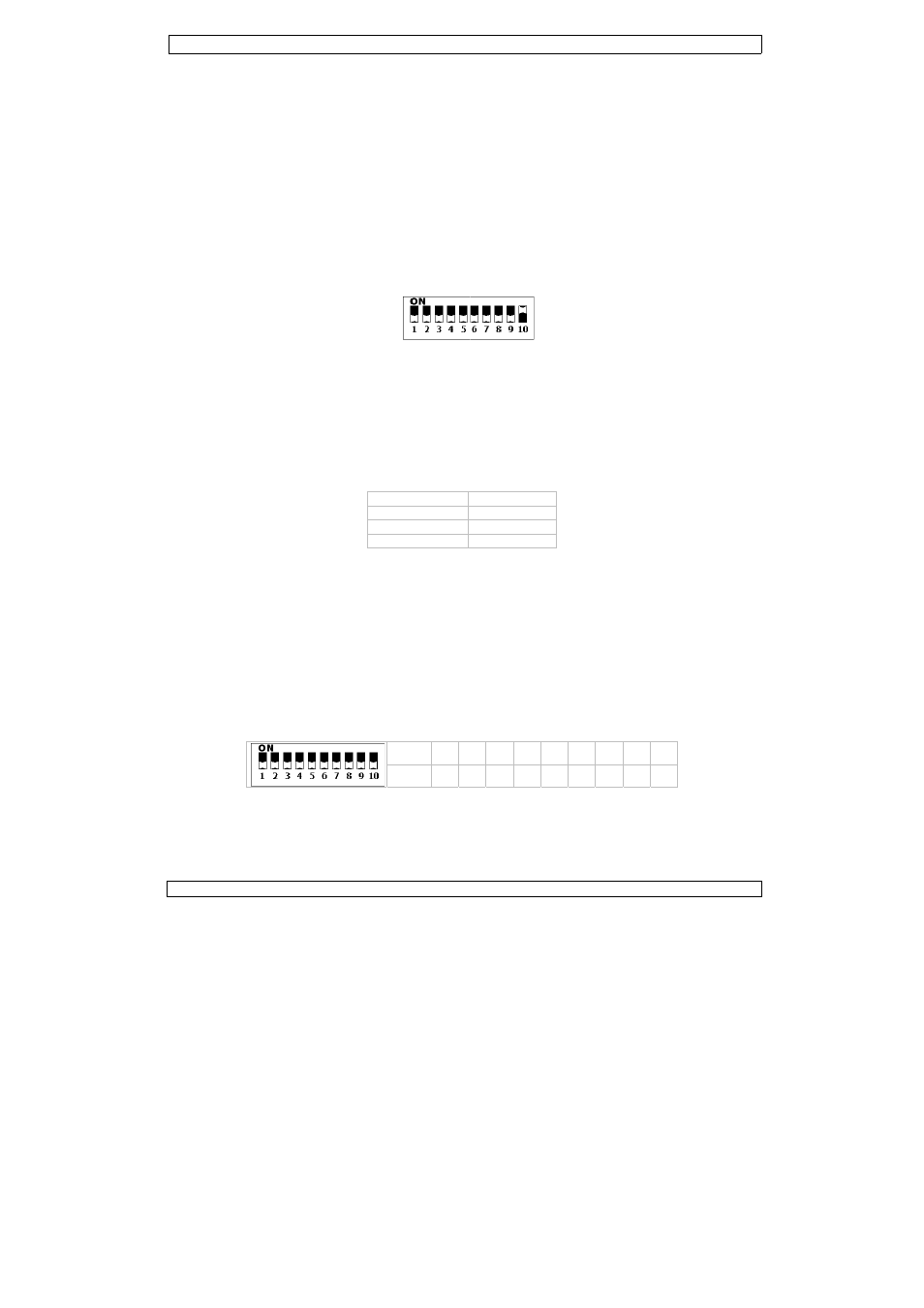
t DIP switches 7
t the colour cha
mode
nnect multiple V
t the master VD
t DIP switch 1 t
l mode (fixed
t DIP switches 8
e: switch 7 is no
ontrolled mo
t DIP switch 10
DMX-controlled
nals. This digita
e DMX controller
dividual address
hen all devices h
rticular channel
multaneously. If
mber. Changing
case of the 7-ch
H1~7), the seco
e the DIP switch
fer to the table
s no flammable
lectrician carry
e to the mains w
d circuit and can
el is used solely
as to be approve
s of the beam r
tighten the kno
s on page 2 of th
an operate in fiv
DMX controlled
mode
to the ON posit
ne [5] sensitivit
7, 9 and 10 to O
anging speed wi
VDPL110CC’s a
DPL110CC to so
o ON to enable
d output)
8, 9 and 10 to O
D
ot used.
de
to the OFF pos
d devices need a
al start address
r. The same sta
can be set for
have the same a
. In other words
you set individ
g the settings of
hannel VDPL11
ond unit to 8 (1
hes to set the a
below for an ov
VDPL11
5
material within
out the electric
with the power
nnot be run off
for 0% to 100%
ed by an expert
release both slid
obs.
his manual.
ve modes: soun
d mode.
tion to enable so
ty with the sens
ON to enable au
th switches 1 to
as described in
ound controlled
slave mode.
ON to enable ma
DIP switch
1, 2 ON
3, 4 ON
5, 6 ON
ition to enable D
a digital start ad
is the channel n
arting address ca
every device.
address, all the
s: changing the
ual addresses, e
f one channel w
10CC, you will h
+ 7) (CH8~14)
ppropriate DMX
switch 1
2
value 1
2
verview of the c
10CC
a 50cm radius
al connection.
plug. All fixture
a rheostat or di
% switch.
t before the dev
der-knobs at the
nd controlled,
ound controlled
sitivity knob [6]
tomatic mode.
o 6.
§6.b.
or automatic m
anual mode.
output
red LEDs
green LEDs
blue LEDs
DMX controlled
ddress so that t
number from w
an be used for a
units will “listen
settings of one
each device will
will only affect th
have to set the s
), the third to 1
X address.
2 3 4 5
2 4 8 1
ontrol signals p
of the device an
es must be powe
immer circuit, e
vice is taken into
e bottom of the
automatic mo
mode.
].
mode.
mode.
he correct devic
hich the device
a whole group o
n” to the contro
e channel will af
“listen” to a se
he device in que
start address of
5 (8 + 7) (CH1
5 6 7 8
6 32 64 12
er channel.
Re
©Vellem
nd there is suffi
ered directly off
even if the rheos
o service.
device. Set the
ode, slave mod
ce responds to t
starts to “listen
of devices or an
ol signal on one
ffect all devices
eparate channel
estion.
f the first unit to
5~21), and so o
8 9
28 256
ev. 01
man nv
cient
f a
stat
e
de,
the
n” to
o 1
on.