Velleman VDP1500SM User Manual
Page 4
05.01.201
• Only u
electro
4. Mo
• Have t
norms
• The ca
deform
• The in
• Never
technic
• Install
• Overhe
installa
attemp
in inju
• Adjust
• Make s
• Have a
• Conne
• The in
5. Des
Refer to t
A. contr
1
pow
2
fuse
3
DIP
B. settin
1
pow
2
out
3
MIN
4
SEC
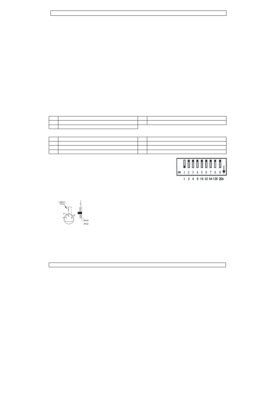
6. DM
DIP S
Pull do
shown
DMX5
Conne
the ma
linking
DMX5
DMX5
All DM
signals
DMX c
VDP15
You ca
every
0
use the device fo
oshocks, crash,
ounting the
the device insta
.
arrying construc
ming.
stallation must
stand directly b
cian check the d
the device in a
ead mounting re
ation material to
pt to install the
ries.
t the desired inc
sure there is no
a qualified elect
ct the device to
stallation has to
scription
the illustrations
ol unit
wer on/off
e
P switches
ngs
wer LED
put LED
NUTES: time be
CONDS: time of
MX512 Mode
witch Setting
own in the arrow
on the diagram
512 Connection
ct the provided
ale 3-pin XLR in
g. The linking ca
512 Chain with
512 Start Addr
X-controlled de
s. This digital st
controller. Enter
500SM.
an use the same
device.
or its intended p
etc. Using the d
Device
lled by a qualifi
ction must be ab
always be secu
below the device
device once a ye
location with fe
equires extensiv
o be used… Hav
device yourself
clination angle v
o flammable mat
rician carry out
o the mains with
o be approved b
s on page 2 of th
tween two burs
f one burst
e
w direction to tu
m is preset as “1
ns
XLR cable to th
nput of the VDP
able should be tw
h Terminator
A DMX termina
run a long dist
terminator pre
The DMX term
and 3, which is
chain. Please s
ess Selection
vices need a dig
tart address is t
r the correct num
e starting addre
VDP150
4
purpose. All oth
device in an una
ed person, resp
ble to support 1
red with a seco
e when it is bein
ear and once be
ew passers-by t
ve experience:
ve the material
f if you lack thes
via the mounting
terial within a 0
the electric con
h the power plug
by an expert bef
his manual.
sts
urn on. The add
1”.
he female 3-pin
P1500SM. Multi
wo core, screen
ator is recomme
tance or is in an
events corruptio
inator is simply
s then plugged
see illustrations
gital start addre
he channel num
mber and read i
ss for a whole g
00SM
er uses may lea
authorised way
pecting EN 6059
0 times the wei
ndary attachme
ng mounted, re
efore you bring
that is inaccessi
calculating work
and the device
se qualifications
g bracket and ti
0.5 m radius of t
nnection.
g. Do not conne
fore the device
4
DMX input
5
controller
5
MANUAL:
6
TIMER LED
7
READY LE
8
VOLUME:
ress switch
XLR output of y
ple VDP1500S
ned cable with X
ended for install
n electrically noi
n of the digital
an XLR plug wi
into the XLR ou
to the left.
ess so that the c
mber from which
it from the disp
group of devices
ad to short circu
will void the wa
98-2-17 and all
ight of the devic
ent e.g. a safety
moved or servic
it into service.
ble to unauthor
kload limits, det
itself checked r
s as improper in
ighten the brack
the device.
ect it to a dimm
is taken into se
t/output
input
manual smoke
D
D
volume of smok
your controller a
SMs can be linke
XLR input and ou
lations where th
sy environment
control signal b
ith a 120Ω resis
tput socket of t
correct device r
h the device sta
lay located on t
s or enter an ind
Rev
©Vellema
uits, burns,
arranty.
other applicable
ce for 1 hour wi
y cable.
ced. Have a qua
rised persons.
termining the
egularly. Do no
nstallation may r
ket screws.
ing pack.
rvice.
output
ke output
and the other si
ed through seria
utput connector
he DMX cable ha
t (e.g. discos). T
y electrical nois
stor between pin
the last device in
esponds to the
rts to “listen” to
he backside of t
dividual one for
v. 01
an nv
e
thout
alified
t
result
ide to
al
rs.
as to
The
se.
ns 2
n the
o the
the
r