2 information on foundation fieldbus, Block diagram, measured value processing, Diagram, adjustment – VEGA VEGABAR 51 Foundation Fieldbus User Manual
Page 54: Fig. 29: adjustment vegabar 51
54
10 Supplement
VEGABAR 51 • Foundation Fieldbus
36715-EN-130321
Ʋ External housing
IP 65, IP 66/IP 68 (0.2 bar)
Overvoltage category
III
Protection class
II
Approvals
Instruments with approvals can have different technical data depending on the version.
For that reason the associated approval documents of these instruments have to be carefully
noted. They are part of the delivery or can be downloaded under www.vega.com via "VEGA Tools"
and "serial number search" as well as via "Downloads" and "Approvals".
10.2 Information on Foundation Fieldbus
Block diagram, measured value processing
The following illustration shows the Transducer Block and Function block in simplified form.
t
i
Simulat
e
ALARMS
Out
PV
FIELD-VALUE
Mode & Status
PVF-TIME
LO
W
-C
UT
O
FF
L-TYP
E
OUT-SCALE
PV-SCALE
DIRECT
INDIRECT
INDIRECT
SQRT
bar
%
Lin%
Primary
Value
Secondary
Value 1
Secondary
Value 2
Sensor mounting
correction
AI 2
AI 3
AI 1
TB
Temperature
Sensor_Value
Linearization
adjustment
Channel = 1: Primary Value
Channel = 2: Secondary Value 1
Channel = 3: Secondary Value 2
Channel = 4: Temperature
Fig. 28: Transducer Block VEGABAR 51
TB Transducer Block
AI Function Block (AI =Analogue Input)
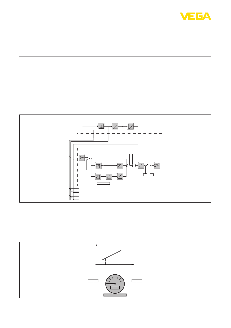
Diagram, adjustment
The following illustration shows the function of the adjustment:
Secondary_value_2
scale_in_0 scale_in_100
Sensor_value
0 %
100 %
bar
0,500
-0,500
0
%
100
%
scale_in_100
scale_in_0
Fig. 29: Adjustment VEGABAR 51