2 mounting instructions – VEGA VEGAPULS 66 (≥ 2.0.0 - ≤ 3.8) standpipe ver. 4 … 20 mA_HART two-wire User Manual
Page 14
M
ake sure that all parts of the instrument in contact with the measured
product, especially the sensor element, process seal and process
fi
tting, are suitable for the existing process conditions such as process
pressure, process temperature as well as the chemical properties of
the medium.
Y
ou can find the specifications in chapter "Technical data" in the or on
the type label.
4.2 Mounting instructions
B
y using the standpipe version, the influence of turbulence and vessel
installations, such as e.g. heating spirals or agitators, is excluded. If
turbulence or vigorous product movement occurs in the vessel, long
standpipe antennas should be fastened to the vessel wall.
T
he standpipe antenna must extend all the way down to the requested
min. level, as measurement is only possible within the tube. If a good
mixing of the product is important, you should use a version with
perforated surge pipe.
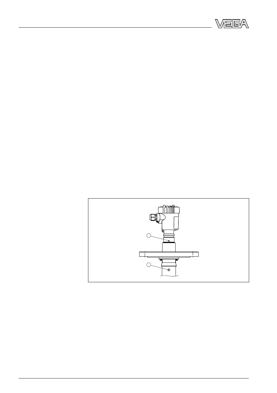
I
f the flange of VEGAPULS 66 was separated from the tube during
transport, make sure when mounting that the polarisation marking is in
one plane to the vent hole. Take care that the plastic tip of the radar
sensor is not damaged during transport.
1
2
Fig. 5: Polarisation marking
1
Marking of the polarisation direction
2
Vent hole ø 8 mm (0.3 in)
Suitability for process
conditions
Mounting
14
VEGAPULS
66
standpipe version • 4 … 20 mA/HART two-wire
4 M
ounting
28741
-EN
-090305