VEGA VEGATOR 536 Ex User Manual
Page 12
12
VEGATOR 536 Ex
Fault monitoring
The measuring system is monitored continu-
ously. The following criteria are checked:
- two-wire line on line break and shortcircuit
- interruption of the connection line to the
piezoelements
- corrosion or damage of the tuning fork
(vibrating rod)
- break age of the tuning fork (vibrating rod)
- stop of vibration
- vibrating frequency too low
- corrosive medium penetrated into the sen-
sor
Test key
A function test can be carried out with meas-
uring systems in conjunction with two-wire
oscillators (VIB E50Z(Ex), SW E60ZEx,
SW E82ZEx).
The VEGATOR 536 Ex signal conditioning
instrument has an integral test key. The test
key is lowered in the front plate of the signal
conditioning instrument. Press the test key
with a suitable object (screwdriver, pen etc.).
By pressing the test the key measuring sys-
tem is checked according to the following
criteria:
- switching function of the switching outputs
- potential separation of the outputs
- signal processing of the signal conditioning
instrument.
Set-up
After pressing the test key, the complete
measuring system is checked for correct
function. During the test, the following operat-
ing conditions are simulated:
- fault signal
- empty signal (only with VEGASWING)
- full signal.
Check if all three switching conditions occur
in the correct sequence and the stated dura-
tion. If this is not the case, there is a failure in
the measuring system (see 5.2 Failure re-
moval).
Please note that the connection instruments
are activated during the function test, which
means that you can check the correct func-
tion of the measuring system.
Due to this fault monitoring, the combination
of the following instruments corresponds to
classes 1 to 3 (AK 3) acc. to DIN 19 251.
AK 3 means that the system is fail safe.
- VEGASWING 61Ex, 63Ex, 81AEx, 83AEx
- SW E60ZEx, SW E82ZEx oscillator
- VEGATOR 536 Ex, 537 Ex, 636 Ex signal
conditioning instrument
VEGAVIB also passes the function test, how-
ever it is not approved acc. to WHG and
AK acc. to DIN 19 251.
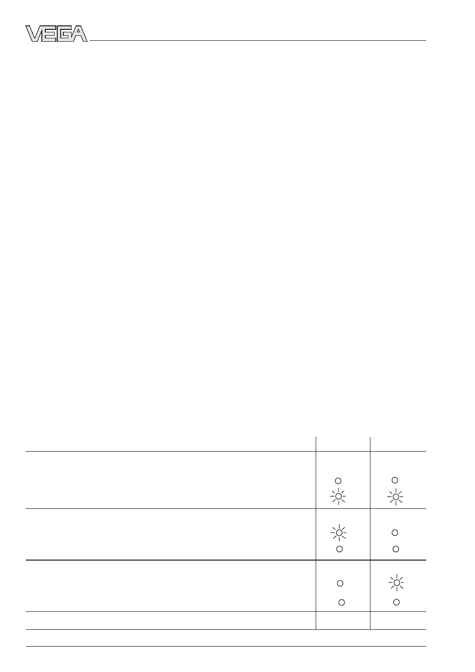
Test course
A-mode
B-mode
1 Simulation of a fault signal (after release of the key approx. 3 s)
1)
Level relay
deenergised
Fail safe relay
deenergised
2 Simulation of an empty signal (approx. 1,5 s)
only with VEGASWING
Level relay
energised
Fail safe relay
energised
3 Simulation of a full signal (approx. 1,5 s)
Level relay
deenergised
Fail safe relay
energised
4 Return to the actual operating condition (covered/uncovered)
1)
As long as the test key is pressed, the instrument remains at failure