3 technical data – VEGA VEGABAR 15 User Manual
Page 4
4
VEGABAR 15
Product description
1.3 Technical data
Power supply
Supply voltage
10 … 30 V DC
Permissible residual ripple
U
SS
£ 1 V
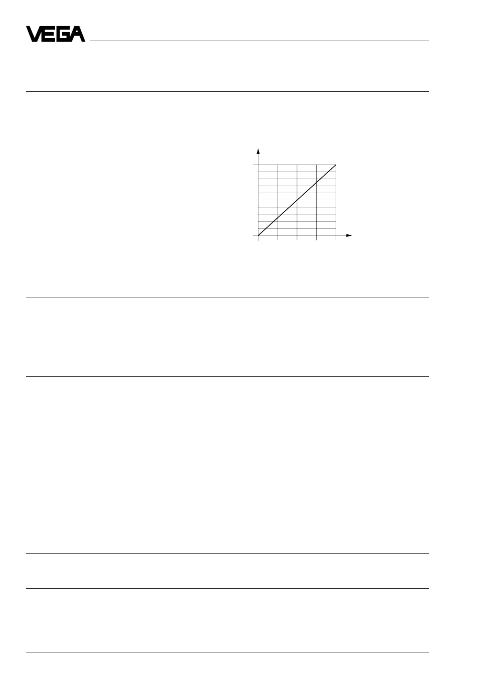
Max. permissible load
depending on the supply voltage
(see load diagram)
10
500
1000
15
20
25
30
0
Load R
Ltotal
in Ohm
Supply voltage U
H
in Volt
Output signal
The analogue 4 … 20 mA output signal (measuring signal) is transmitted together with the
power supply via one two-wire cable.
Range
3.5 … 23 mA
Current limitation
approx. 28 mA
Accuracy
1)
(typical values under reference conditions, all statements relate to the nominal
measuring range)
Determination of characteristics
limit point adjustment acc. to DIN 16 086
Characteristics
linear
Deviation in characteristics
- inner sensor element
< 0.3 %
- flush version
< 0.2 %
Hysteresis
< 0.1 %
Repeatability
< 0.1 %
Average temperature coefficient of the
zero signal
2)
< 0.2 %/10 K
Long-term drift of the zero signal
< 0.25 % per year
Calibration position
upright, diaphragm points downwards
Vibration resistance
mechanical vibrations with 4 g and
5 … 100 Hz, tested acc. to the regulations of
German Lloyd GL-characteristics 2
Characteristics
Delay time (0 … 63 %)
< 4 ms
Ambient conditions
Ambient temperature
-40°C … +85°C
Storage and transport temperature
-50°C … +85°C
Product temperature
-40°C … +100°C