3 electrical connection, 1 connection instructions, 2 wiring plan – VEGA Capacitive electrodes EL 4 … 20 mA - Compact User Manual
Page 22
22
Capacitive electrodes EL 4 … 20 mA - Compact
22652-EN-020809
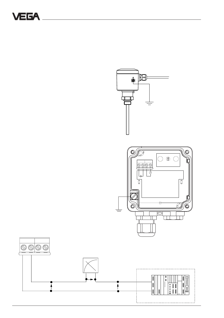
3.2 Wiring plan
Note
The oscillator is independent of the electrode
and can be exchanged on site.
Electrical connection
3 Electrical connection
3.1 Connection instructions
Note
Switch off the power supply before starting
connection work.
Connect the supply voltage according to the
following connection diagrams.
A multimeter can be connected to terminals 3
and 4 for setup. This connection is not suitable
for an indicating instrument.
Note
If strong electromagnetic interference is ex-
pected, we recommend using screened ca-
ble. The screening of the cable should only be
earthed on one end, i.e. the sensor end (elec-
trode).
Always connect the electrode to vessel
ground (PA). For this purpose there is a termi-
nal on the side of the housing. This connection
is also used to supply the ground reference
potential as well as to drain off electrostatic
charges.
+
–
4 … 20 mA
Terminals
Sensor
4
3
2
1
+ - + -
Ri < 250
+
–
with bridge:
12 …36 V
without bridge:
13 … 36 V
4
3
2
1
+
-
8
0
2
6
4
+ - + -
mA
U = 12 … 36 V
U
K
U
A
U
H
4 … 20 mA
U = 12 … 36 V
analogue/digital
indicating instrument