VEGA VEGAPULS 62 (≥ 2.0.0 - ≤ 3.8) 4 … 20 mA_HART four-wire User Manual
Page 19
d
h
max.
d
1½"
50 mm/2"
80 mm/3"
100 mm/4"
150 mm/6"
200 mm
250 mm
300 mm
500 mm
800 mm
h
max.
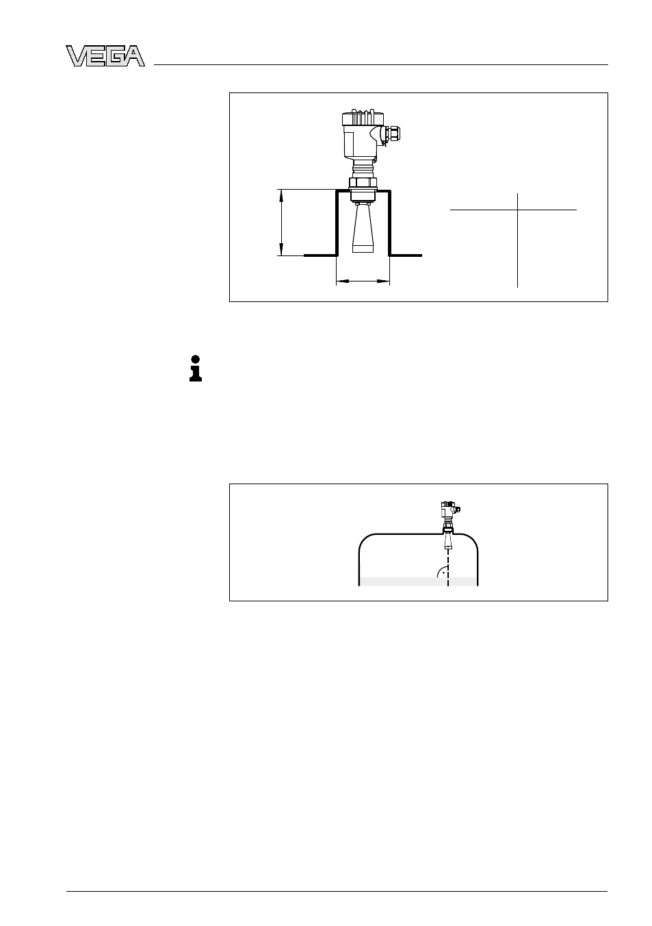
Fig. 11: Deviating socket dimensions
Tip:
VEGAPULS
62
is optionally also available with antenna extension.
H
ence the antenna length can be selected such that the antenna end
protrudes 10 mm (0.4 in) out of the socket.
A
lign the sensor in liquids as vertical as possible to the product surface
to achieve optimum measuring results.
Fig. 12: Alignment in liquids
T
he mounting location of the radar sensor should be a place where no
other equipment or fixtures cross the path of the microwave signals.
V
essel installations such as, for example, ladders, limit switches,
heating spirals, struts, etc. can cause false echoes that get super-
imposed on the useful echo. Make sure when planning your measuring
site that the radar sensor has a "clear view" to the measured product.
I
n case of existing vessel installations, a false echo storage should be
carried out during setup.
I
f large vessel installations such as struts or supports cause false
echoes, these can be attenuated through supplementary measures.
S
mall, inclined sheet metal baffles above the installations scatter the
radar signals and prevent direct interfering reflections.
Sensor orientation
Vessel installations
VEGAPULS
62 • 4 … 20
mA/HART four-wire
19
4 M
ounting
28440
-EN
-090305