2 exchange of electronics – VEGA VEGABAR 41 4 … 20 mA User Manual
Page 27
VEGABAR 41 (4 … 20 mA)
27
Instrument modification
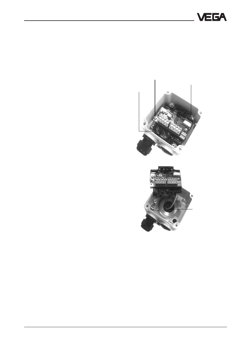
6.2 Exchange of electronics
You first have to remove the adjustment mod-
ule, as described in chapter "6.1 Exchange
of adjustment modules“, in order to exchange
the complete electronic module of VEGABAR.
• Remove the ground screw and the two
smaller fixing screws connecting the elec-
tronic unit with the housing
• Pull the electronic unit to the top and pull
out the plug connection
• Proceed in reverse sequence when install-
ing the new electronics module
Note:
No new adjustment is necessary after ex-
changing the electronics module. When
switching on the first time (connection of the
supply voltage) after exchange of the elec-
tronics units, it takes approx. 20 s until the
current measured value is displayed.
Ground
screw
Fixing screw
Fixing screw
Plug
connection
Exchange of the adjustment module
Removal of the adjustment module
•
Separate VEGABAR from the power
supply
•
Loosen the screws on the upper side of
the housing and remove the cover or the
display module
•
Loosen connection cables from the termi-
nals, if necessary pull out the plug con-
nection of the display module
•
Remove the two screws of the adjustment
module
•
Remove adjustment module and pull out
plug connection
Insertion of an adjustment module
•
Plug the plug connection of the new ad-
justment module into the plug-in socket of
the sensor electronics
•
Fasten the new adjustment module
•
Reconnect the connection cables, if nec-
essary, also the cable from the display
module
•
Close cover or display module of VEGA-
BAR
•
Reconnect VEGABAR to power supply