Control of alternating current loads, Contactless electrical switch (swing e72 c), A/b-mode – VEGA VEGASWING 75A User Manual
Page 12
12
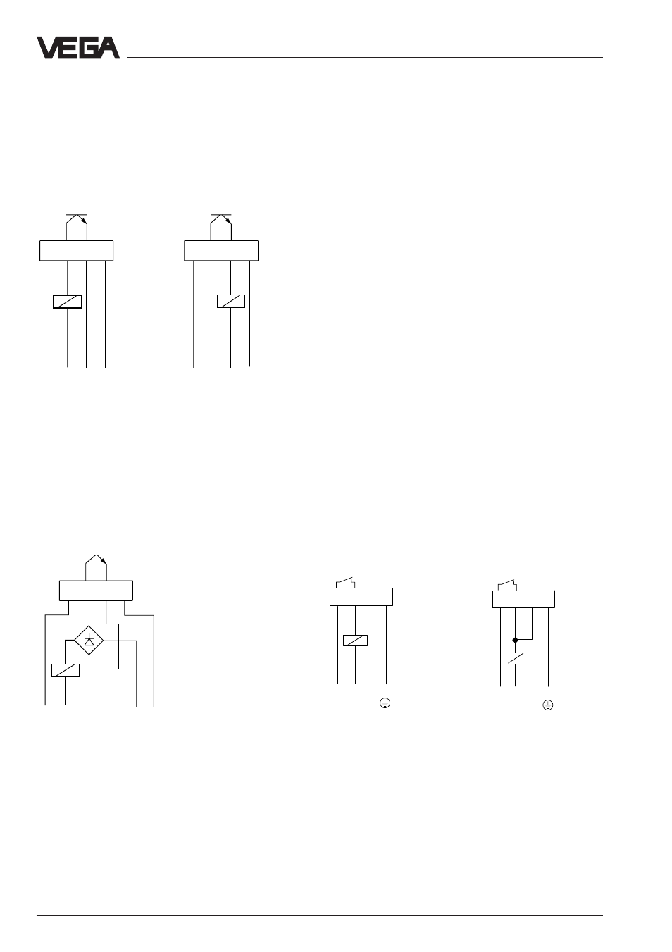
VEGASWING 71A and 75A
The transistor switches a second, galvani-
cally isolated voltage source to the binary
input of a PLC or to an electrical load.
Mode A
For mode B you have to switch the polarity of
terminals 1 and 4.
Control of alternating current loads
The transistor switches a galvanically sepa-
rated alternating voltage 10 … 42 V AC to a
load.
Mode A
NPN action
PNP action
–
+
1
2
3
4
–
+
1
2
3
4
+
+
–
–
–
+
1
2
3
4
~
~
U
B
U
B
U
B
U
B
U
B
U
B
Note
The transistor outputs of several VEGAS-
WING 71A or 75A can be switched in series
or in parallel to connect their signals logically.
The connection must be made such that
terminal 2 always has a higher voltage com-
pared to terminal 3.
Electrical connection
Contactless electrical switch
(SWING E72 C)
Power supply 20 … 250 V AC,
50/60 Hz or 20 … 250 V DC
(for further information see the following con-
nection examples as well as the technical
data)
For direct control of relays, contactors, mag-
net valves, warning lights, horns etc. the
instrument must not be operated without
connected load (switching in series), as the
oscillator can be destroyed when connected
directly to mains. Not suitable for connection
to low voltage PLC inputs.
The domestic current is temporarily lowered
below 1 mA after switching off the load so
that contactors, the load current of which is
lower than the permanently flowing domestic
current of the electronics, are reliably
switched off.
A/B-mode
Mode A
Mode B
Max. detection,
Min. detection,
overfill protection
dry run protection
-
1
2
3
4
+
L1 N
In mode A, terminal 3 remains free. Therefore
do not connect a cable to terminal 3, not even
up to the next junction box, since the cable
can pick up interfering signals.
-
1
2
3
4
+
L1
N