Setup – V-Tech DT592 Manual User Manual
Page 12
-10-
6.Setup
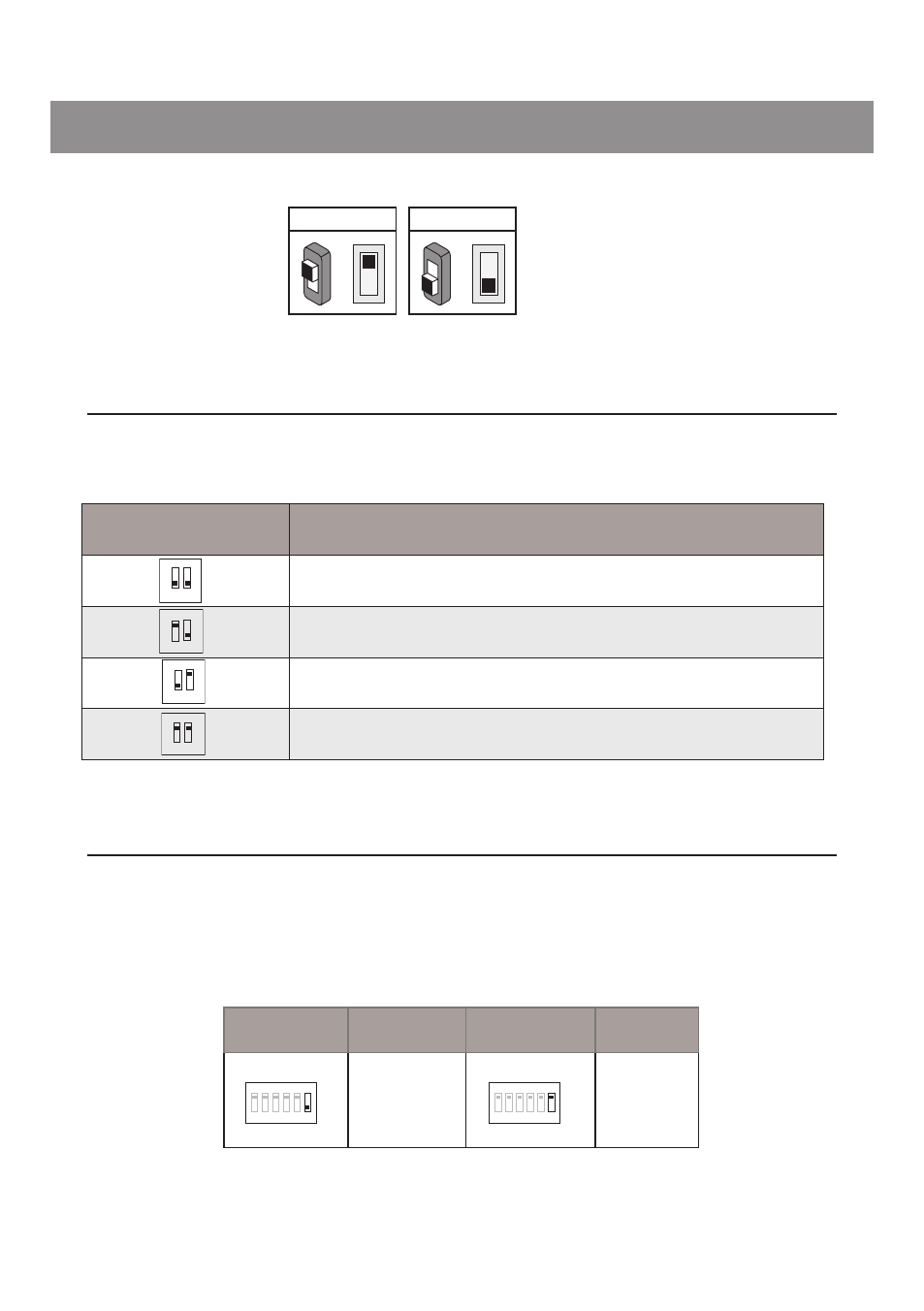
6.2 DIP Switches Settings of Monitor
6.1 DIP Switches Settings of Doorstation
Total 2 bits on the DIP switches can be configured.The switches can be modified either before or after
installation.
Bit state
Descriptions
Default setting, ID = 0(00), set to the first Door Station.
ID = 1(10), set to the second Door Station.
ID = 2(01), set to the third Door Station.
ID = 3(11), set to the fourth Door Station.
1 2
ON
1 2
ON
1 2
ON
1 2
ON
There are 6 bit switches in total. The DIP switches are used to configure the User Code for each
Monitor.
ON(1)
=
OFF(0)
=
ON
ON
Bit-6 is used to set video impedance,it should be set to ON if the Monitor is in the end of the line(bus),
otherwise set to OFF.
Bit state
Setting
Bit state
Setting
The monitor is
not at the end
of the bus.
The monitor
is at the end
of the bus.
1 2 3 4 5
6
ON
1 2 3 4 5
6
ON