Parts and functions, Lock control jumper, Doorstation code dip – V-Tech DT597 Info User Manual
Page 2: Main connect port, S1+, s2
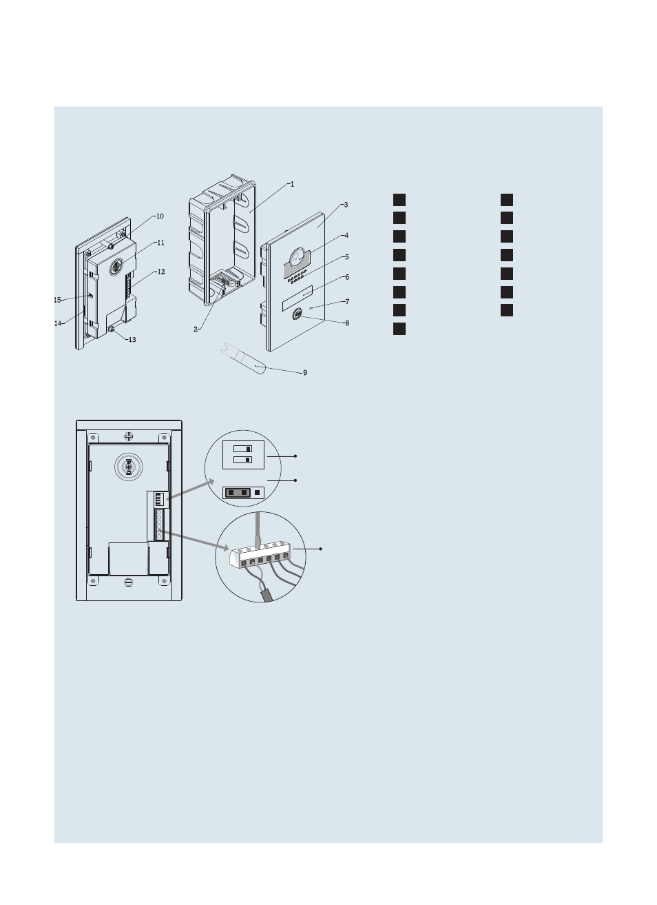
1. Parts and Functions
Mounting box
Front panel
Plastic bracket
Speaker
Camera lens
Name plate
1
2
3
4
5
6
Microphone
7
Call button
8
Spanner
Camera adjustment
Fixed axis B
Fixed axis A
Connection port
Microphone
9
10
11
12
13
14
Signal adjustment
15
BUS PL
S1+ S2+
S-
1
2
ON
Lock Control Jumper
Doorstation Code DIP
Main Connect Port
1 2 3
Lock Control Jumper:
To select the lock type: see 5.2.1 , 5.2.2
Doorstation Code DIP:
Total 4 doorstations can be supported,see 6.1
Main Connect Port:
To connect the bus line and the electronic locks.
BUS:
Connect to the bus line, no polarity.
PL:
External lock power input, connect to the power positive(power +).
S1+, S2+:
Lock power(+) output, to connect 2 locks.
S-:
Lock power(-) output, connect to the power(-) input of locks(only when using the camera to
power the locks, if using the external power supply for the locks, the S- will not be connected).