Delivery scope, Intended use, Technical data – Bosch GWS 780 C Professional User Manual
Page 15: Declaration of conformity, Noise/vibration information
English | 15
Bosch Power Tools
1 609 92A 0EK | (22.8.13)
Delivery Scope
Angle grinder, protection guard, auxiliary handle.
Special protection guards, application tools and other acces-
sories shown or described are not part of the standard deliv-
ery scope.
A complete overview of accessories can be found in our ac-
cessories program.
Intended Use
The machine is intended for roughing metal, stone and ceram-
ic materials and for drilling tiles.
For cutting with bonded abrasives, a special cutting guard
(accessory) must be used.
When cutting in stone, provide for sufficient dust extraction.
Together with the hand guard (accessory), the machine can
be used for brushing and grinding/sanding with elastic sand-
ing plates.
The machine is suitable only for working without water.
Technical Data
The technical data of the machine are listed in the table on
page 244
–246.
The values given are valid for a nominal voltage [U] of 230 V.
For different voltages and models for specific countries,
these values can vary.
Declaration of Conformity
We declare under our sole responsibility that the product de-
scribed under “Technical Data” is in conformity with the fol-
lowing standards or standardization documents: EN 60745
according to the provisions of the directives 2011/65/EU,
2004/108/EC, 2006/42/EC.
Technical file (2006/42/EC) at:
Robert Bosch GmbH, PT/ETM9,
D-70745 Leinfelden-Echterdingen
Robert Bosch GmbH, Power Tools Division
D-70745 Leinfelden-Echterdingen
23.08.2013
Noise/Vibration Information
The measured values of the machine are listed in the table on
page 244
–246.
Noise and vibrational values (vector sum of three directions)
determined according to EN 60745.
The vibration level given in this information sheet has been
measured in accordance with a standardised test given in EN
60745 and may be used to compare one tool with another. It
may be used for a preliminary assessment of exposure.
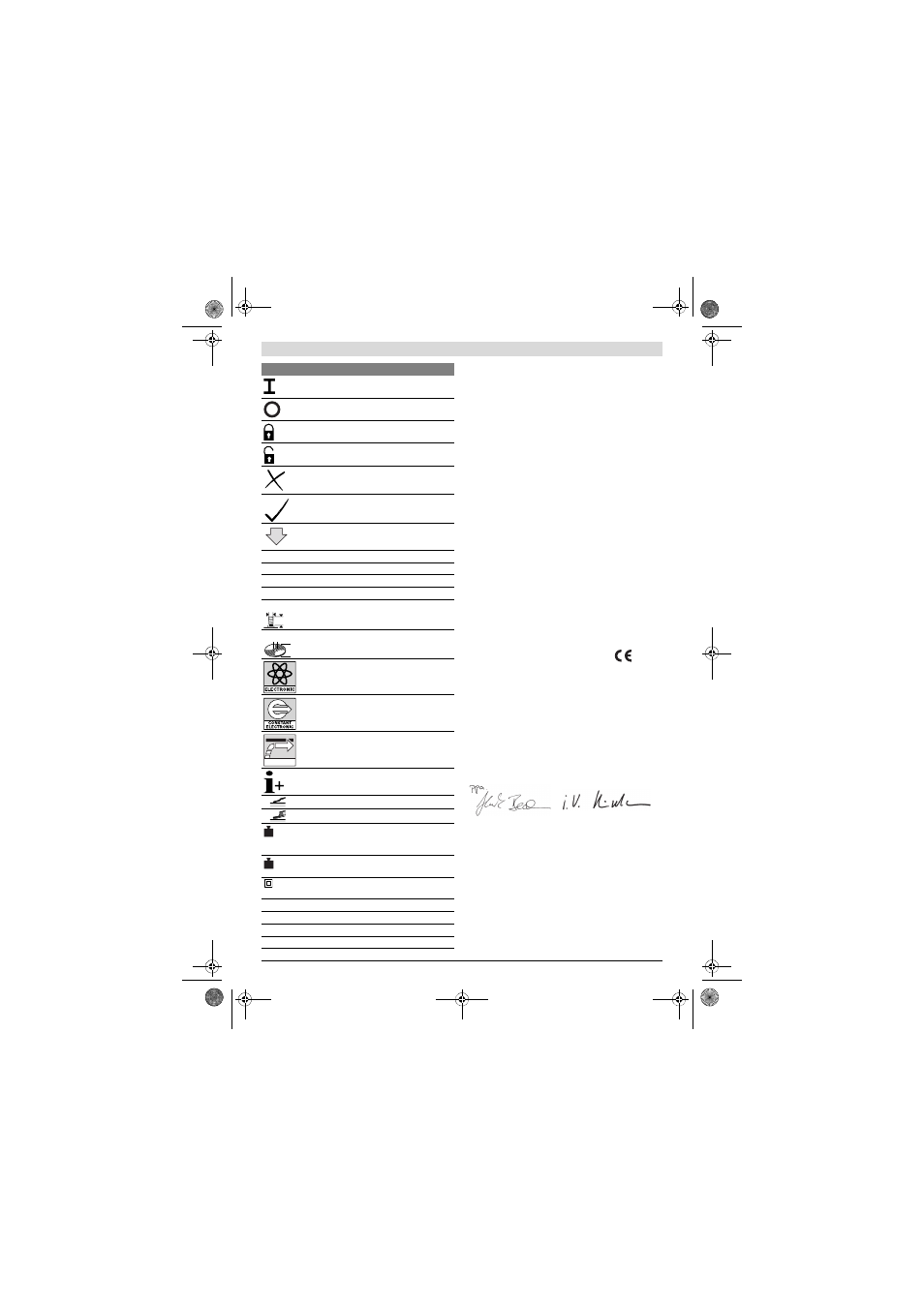
Switching On
Switching Off
On/Off switch lock-on
Releasing the lock-on function of the
On/Off switch
Prohibited action
Permitted action
Next step of action
P
1
Rated power input
P
2
Output power
n
Rated speed
n
v
Speed control adjustment
l = Grinder spindle length
d
1
= Grinder spindle diameter
D = Max. grinding disc diameter
d
2
= Inner disc diameter
Speed preselection
Constant Electronic Control
Reduced starting current
Additional information
Surface grinding
Grinding/sanding with sanding sheet
Weight according to EPTA-Procedure
01/2003 with vibration-damping auxil-
iary handle
Weight according to EPTA-Procedure
01/2003 with standard-auxiliary handle
/
II
Symbol for protection class
II (com-
pletely insulated)
L
wA
Sound power level
L
pA
Sound pressure level
K
Uncertainty
a
h
Vibration total value
Symbol
Meaning
d
1
l
d
2
D
1
2
Henk Becker
Executive Vice President
Engineering
Helmut Heinzelmann
Head of Product Certification
PT/ETM9
OBJ_BUCH-161-007.book Page 15 Thursday, August 22, 2013 3:50 PM