Bosch PCM 7 User Manual
Page 31
English | 31
Bosch Power Tools
1 609 929 U75 | (19.7.10)
Working Advice
General Sawing Instructions
f
For all cuts, it must first be ensured that the
saw blade at no time can come in contact
with the fence, screw clamps or other ma-
chine parts. Remove possibly mounted aux-
iliary stops or adjust them accordingly.
Protect the saw blade against impact and shock.
Do not subject the saw blade to lateral pressure.
Do not saw warped/bent workpieces. The work-
piece must always have a straight edge to face
against the fence.
Long workpieces must be underlaid or support-
ed at their free end.
Marking the Cutting Line (see figure J)
A laser beam indicates the cutting line of the
saw blade. This allows for exact positioning of
the workpiece for sawing, without having to
open the retracting blade guard.
– For this, switch the laser beam on with the
switch 20.
– Align the cutting mark on your workpiece
with reference to the right-hand edge of the
laser line.
Position of the Operator (see figure K)
f
Do not stand in a line with the saw blade in
front of the machine. Always stand aside of
the saw blade. This protects your body
against possible kickback.
– Keep hands, fingers and arms away from the
rotating saw blade.
– Do not cross your arms when operating the
tool arm.
Permissible Workpiece Dimensions
Maximal workpiece sizes:
Minimal workpiece sizes
(= all workpieces that can be clamped left or
right from the saw blade with the supplied ma-
terial clamp 14): 100 x 40 mm (length x width)
Cutting capacity, max. (0°/0°): 50 mm
Cutting Off
– Firmly clamp the workpiece as appropriate
for its dimensions.
– Adjust the requested horizontal and/or verti-
cal mitre/bevel angle.
– Switch on the machine.
– Press lever 3 and slowly guide the tool arm
downward by handle 1.
– Saw through the workpiece applying uniform
feed.
– Switch off the machine and wait until the
saw blade has come to a complete stop.
– Guide the tool arm slowly upward.
Replacing the Insert Plate
The red insert plate 7 can become worn after
long use of the power tool.
Replace defective insert plates.
– Bring the power tool into the working posi-
tion.
– Unscrew screws 8 using a Phillips screwdriv-
er and remove the old insert plate.
– Insert the new insert plate and and screw all
screws 8 in again.
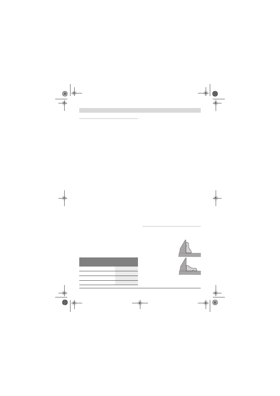
Sawing Profile Strips
Profile strips/mouldings can be sawn in two dif-
ferent ways:
Always make trial cuts with the mitre angle set-
ting first on scrap wood.
Mitre/Bevel Angle
Height x Width
Horizontal
Vertical
0°
0°
50 x 110 mm
45°
0°
50 x 76 mm
0°
45°
37 x 110 mm
45°
45°
37 x 76 mm
– Placed against the fence
– Lying flat on the saw
table
OBJ_BUCH-880-004.book Page 31 Monday, July 19, 2010 11:56 AM