Motherboard layout, English, Hdled reset pled pwrbtn – ASRock P67 Transformer User Manual
Page 2: Cha_fan3, Audio codec, Hdmi_spdif1, Cha_f an2, Speaker1, Pled1, Asrock p67 transformer motherboard
2
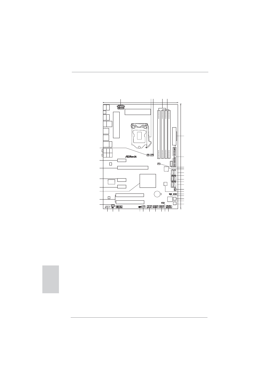
ASRock P67 Transformer Motherboard
Motherboard Layout
English
1
ATX 12V Power Connector (ATX12V1)
21
Dr. Debug
2
1156-Pin CPU Socket
22
Power Switch (PWRBTN)
3
CPU Fan Connector (CPU_FAN1)
23
System Panel Header (PANEL1, White)
4
2 x 240-pin DDR3 DIMM Slots
24
Power LED Header (PLED1)
(Dual Channel: DDR3_A2, DDR3_B2, Blue)
25
USB 2.0 Header (USB12_13, Blue)
5
2 x 240-pin DDR3 DIMM Slots
26
USB 2.0 Header (USB10_11, Blue)
(Dual Channel: DDR3_A1, DDR3_B1, White)
27
USB 2.0 Header (USB8_9, Blue)
6
ATX Power Connector (ATXPWR1)
28
Chassis Fan Connector (CHA_FAN1)
7
Primary IDE Connector (IDE1, Blue)
29
Infrared Module Header (IR1)
8
SATA2 Connector (SATAII_6, Blue)
30
COM Port Header (COM1)
9
Chassis Fan Connector (CHA_FAN3)
31
HDMI_SPDIF Header
10
SATA3 Connector (SATAIII_1, White)
(HDMI_SPDIF1, White)
11
SATA3 Connector (SATAIII_0, White)
32
Front Panel Audio Header
12
SATA2 Connector (SATAII_3, Blue)
(HD_AUDIO1, White)
13
SATA2 Connector (SATAII_2, Blue)
33
Internal Audio Connector: CD1 (White)
14
SATA2 Connector (SATAII_5, Blue)
34
PCI Slots (PCI1-2)
15
SATA2 Connector (SATAII_4, Blue)
35
Intel P67 Chipset
16
Chassis Fan Connector (CHA_FAN2)
36
PCI Express 2.0 x1 Slot (PCIE4, White)
17
64Mb SPI Flash
37
PCI Express 2.0 x1 Slot (PCIE3, White)
18
Chassis Speaker Header (SPEAKER 1, White) 38
PCI Express 2.0 x16 Slot (PCIE2, Blue)
19
Clear CMOS Jumper (CLRCMOS1)
39
PCI Express 2.0 x1 Slot (PCIE1, White)
20
Reset Switch (RSTBTN)
40
Power Fan Connector (PWR_FAN1)
Intel
P67
30.5cm
(12.0
in)
21.8cm (8.6 in)
CMOS
Battery
DDR3_A2
(64
b
it,
2
40-pin
module)
DDR3_A1
(64
b
it,
2
40-pin
module)
DDR3_B2
(64
bit,
240-pin
module)
DDR3_B1
(64
bit,
240-pin
module)
A
T
XPWR1
HDLED RESET
PLED PWRBTN
PANEL1
1
USB8_9
11
IDE1
SA
T
A
II_4_5
SA
T
A
II_2_3
SA
T
A
III_0_1
64Mb
BIOS
P67 Transformer
ATX12V1
DDR3
2600+
PS2
Mouse
Coaxial
SPDIF
PS2
Keyboard
Optical
SPDIF
Clr
CMOS
USB 2.0
T: USB0
B: USB1
Top:
SIDE
SPK
Center:
REAR
SPK
Bottom:
CTR
B
ASS
Top:
LINE
IN
Center:
FRONT
Bottom:
MIC
IN
LAN
PHY
1
HD_AUDIO1
CHA_FAN3
CHA_FAN1
PWRBTN
RSTBTN
Dr.
Debug
AUDIO
CODEC
CD1
Super
I/O
IR1
1
COM1
1
1
HDMI_SPDIF1
USB
3
.0
RoHS
1
2 3
4
5
6
7
8
9
10
11
12
13
14
15
16
17
24
25
23
18
19
20
21
22
26
27
28
29
30
31
32
33
34
35
36
37
38
USB10_11
11
USB12_13
1
CHA_F
AN2
PWR_FAN1
CPU_FAN1
PCIE1
Dual
Channel
PCI Express 2.0 SATA3 6Gb/s
USB 2.0
T: USB4
B: USB5
Top:
RJ-45
PCIE2
PCIE3
PCI1
PCI2
JMicron
JMB363
ErP/EuP Ready
USB 2.0
T: USB6
B: USB7
eSA
T
AII_1
SA
T
A
II_6
SPEAKER1
1
PLED1
1
Designed
in
T
aipei
39
40
USB 3.0
T: USB2
B: USB3
PCIE4
CLRCMOS1
1