Motherboard layout (h61m-vgs / h61m-vs), English, Hdled reset pled pwrbtn – ASRock H61M-VS User Manual
Page 2: Intel h61, Asrock h61m-vgs / h61m-vs motherboard, Erp/eup ready
2
ASRock H61M-VGS / H61M-VS Motherboard
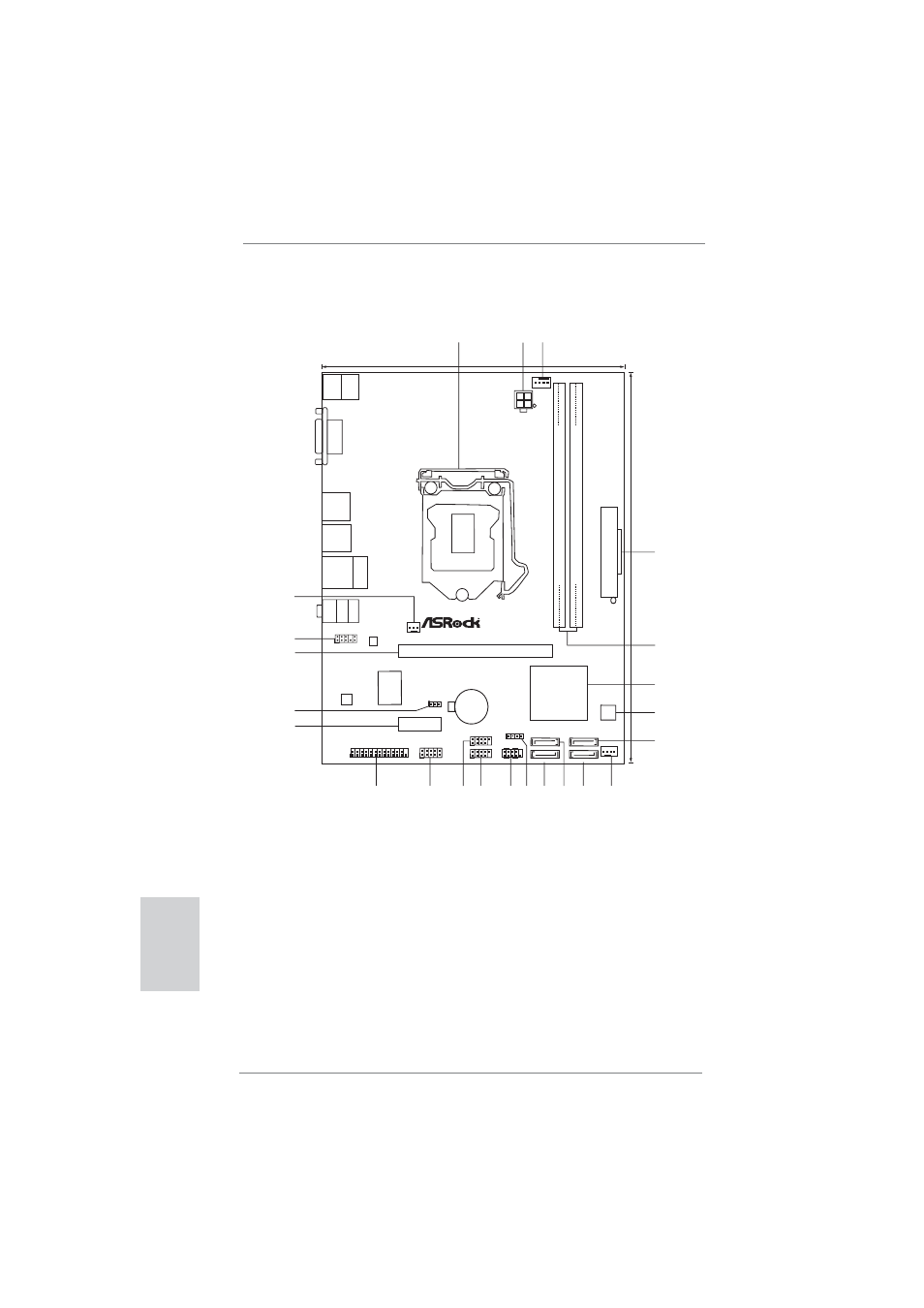
Motherboard Layout (H61M-VGS / H61M-VS)
English
1
1155-Pin CPU Socket
13
Chassis Speaker Header (SPEAKER 1, White)
2
ATX 12V Power Connector (ATX12V1)
14
System Panel Header (PANEL1, White)
3
CPU Fan Connector (CPU_FAN1)
15
USB 2.0 Header (USB6_7, Blue)
4
ATX Power Connector (ATXPWR1)
16
USB 2.0 Header (USB8_9, Blue)
5
2 x 240-pin DDR3 DIMM Slots
17
COM Port Header (COM1)
(Dual Channel: DDR3_A1, DDR3_B1, Blue)
18
Print Port Header (LPT1, White)
6
Intel H61 Chipset
19
PCI Express 2.0 x1 Slot (PCIE2, White)
7
32Mb SPI Flash
20
Clear CMOS Jumper (CLRCMOS1)
8
SATA2 Connector (SATA2_1, Blue)
21
PCI Express 2.0 x16 Slot (PCIE1, Blue)
9
Chassis Fan Connector (CHA_FAN1)
22
Front Panel Audio Header
10
SATA2 Connector (SATA2_0, Blue)
(HD_AUDIO1, White)
11
SATA2 Connector (SATA2_3, Blue)
23
Power Fan Connector (PWR_FAN1)
12
SATA2 Connector (SATA2_2, Blue)
A
T
XPWR1
DDR3_A1
(64
b
it,
2
40-pin
module)
DDR3_B1
(64
bit,
2
40-pin
module)
CPU_FAN1
Intel
H61
CMOS
Battery
17.3cm (6.8 in)
22.6cm
(8.9
in)
ErP/EuP
Ready
Dual
Channel
DDR3
Designed
in
T
aipei
PCI Express 2.0
DX10.1
32Mb
BIOS
Super
I/O
CHA_FAN1
PWR_FAN1
RoHS
1
SPEAKER1
PCIE1
PCIE2
1
HD_AUDIO1
COM1
1
1
LPT1
CLRCMOS1
1
HDLED RESET
PLED PWRBTN
PANEL1
1
LAN
PHY
AUDIO
CODEC
USB6_7
1
USB8_9
1
SATA2_2
SATA2_0
SATA2_3
SATA2_1
ATX12V1
PS2
Keyboard
PS2
Mouse
VGA1
Top:
RJ-45
USB 2.0
T: USB4
B: USB5
USB 2.0
T: USB0
B: USB1
T
op:
LINE
IN
Center:
FRONT
Bottom:
MIC
IN
USB 2.0
T: USB2
B: USB3
1
2
3
4
5
6
7
9
10
11
12
8
14 13
15
16
17
18
19
20
21
22
23