The installation guide of front usb 3.0 panel, English – ASRock Fatal1ty Z68 Professional Gen3 User Manual
Page 39
39
Fatal1ty Z68 Professional Gen3 Series Motherboard
HDMI_SPDIF Header
HDMI_SPDIF header, providing
(2-pin HDMI_SPDIF1)
SPDIF audio output to HDMI
(see p.4 No. 32)
VGA card, allows the system to
connect HDMI Digital TV/
projector/LCD devices. Please
connect the HDMI_SPDIF
connector of HDMI VGA card to
this
header.
Serial port Header
This COM1 header supports a
(9-pin COM1)
serial port module.
(see p.4 No. 29)
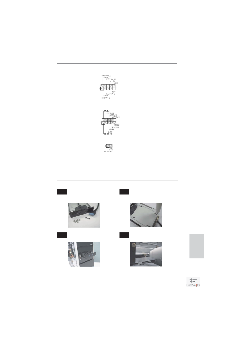
The Installation Guide of Front USB 3.0 Panel
Intall the Front USB 3.0 Panel into
the 2.5” drive bay of the chassis.
Step 3
Step 4
Screw the Front USB 3.0 Panel to
the drive bay with six chassis screws.
Prepare the bundled Front USB 3.0
Panel, four HDD screws, and six
chassis screws.
Step 1
Step 2
Screw the 2.5” HDD/SSD to the Front
USB 3.0 Panel with four HDD
screws.
IEEE 1394 Header
Besides one default IEEE 1394
(9-pin FRONT_1394)
port on the I/O panel, there
(see p.4 No. 24)
is one IEEE 1394 header
(FRONT_1394) on this
motherboard. This IEEE 1394
header can support one IEEE
1394
port.
English