Rmwq 8190, 3 > qd remote control connection & operation – Acnodes RMWQ 8190 User Manual
Page 16
14628 Central Ave,
Chino, CA 91710
tel:909.597.7588, fax:909.597.1939
© Copyright 2013 Acnodes, Inc.
All rights reserved. Product description and product specifications
are subject to change without notice. For latest product information,
please visit Acnodes’ web site at .
RMWQ 8190
8U 19” 1440x900 Rackmount CCTV Monitor
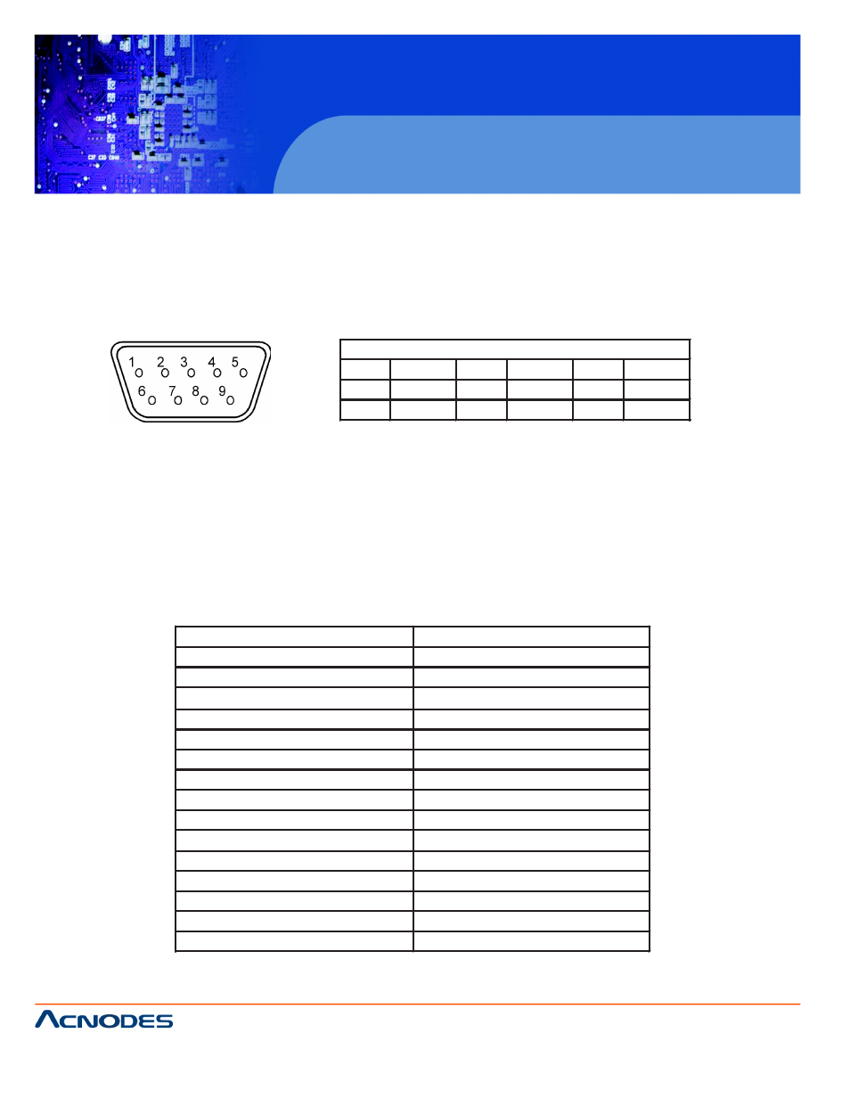
Pin Assignment for Remote Control Connector
1
GND
4
NC
7
VCC
2
RX
5
NC
8
GND
3
TX
6
VCC
9
GND
< 4.3 > QD Remote Control Connection & Operation
The device can be controlled via the male type 9 pin D-sub/RS-232 connector to a computer using ASCII code.
1. Pin assignment of the male type 9 pin D-sub connector:
1
2 3
4 5
6
7 8
9
When a computer is used to control this device through a RS-232 port, pin 6, 7, 8, and 9 must be disconnected to
prevent connecting the VCC and GND signals from the device to the computer. A RS-232 port only uses pin 1, 2,
and 3 for control signal transmission.
2. A terminal or computer can be connected to the male type 9 pin D-sub connector on the real panel from it RS-
232 port to control this device using standard, uppercase ASCII codes.
2.1 The ASCII command codes for the quad are listed in the table below. The transmission protocol is 1200-
baud rate, 8 data bit, 1 start bit, 1 stop bit, and no parity.
Function
ASCII Command Code
Quad Screen Display
E
CH 1
A
CH 2
B
CH 3
C
CH 4
D
Freeze *1
EA, EB, EC, ED
Auto Switching Sequence
F
VCR/Live
G
Key Lock *2
H
Setup Menu *3
GH
Text Select Down *4
(GH) A
Text Select Up
(GH) B
Cursor Left
(GH) C
Cursor Right
(GH) D
Alarm Reset
I