6 installation location, 5 technical data, 7 preparing for unit instal- lation – STIEBEL ELTRON DHF .. C 01.02.2004 - 30.09.2006 User Manual
Page 14
14
2.6 Installation location
The DHF ... C compact control is to
be installed vertically in accordance
with
A
(over-sink or under-sink) in a
closed, frost-free room, as near as possible
to the tap point (a dismantled unit is to be
stored in frost-free conditions, since resi-
dual water always remains in the unit).
Table 3
* Pressure drop values also apply to the minimum flow pressure in accordance with DIN 44851 / Flow rate for heating from 10 °C to 55 °C
(
% # 45 K). A pressure drop of 0.1 MPa (1 bar) is recommended for pipe network dimensioning, in line with DIN 1988 Part 3, Table 4.
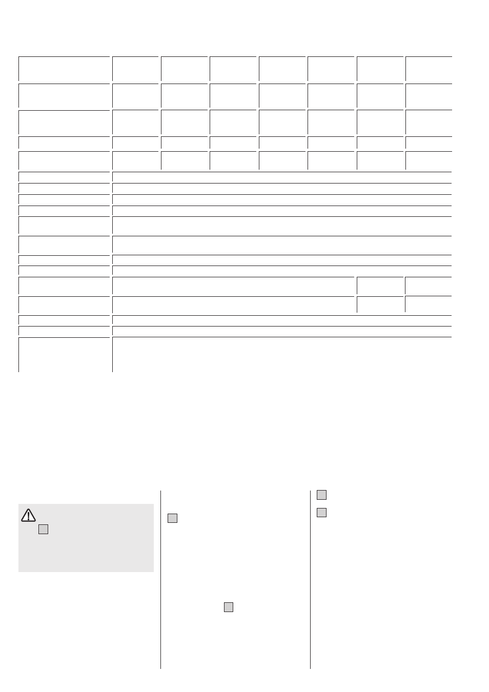
2.5 Technical data
(the data on the unit rating plate are applicable)
Electrical connection
3/PE ~ 400 V
1/N/PE ~
3/PE ~ 230 V
220/230 V
Max. system-impedance
Z max
to DIN EN 61000-3-11
$
0.14
Protection mode to
DIN EN 60529
IP 24
Typ
DHF 13 C
DHF 15 C
DHF 18 C
DHF 21 C
DHF 24 C
DHF 12 C1
DHF 13 C3
compact
compact
compact
compact
compact
compact
compact
control
control
control
control
control
control
control
Heat output
V 400
400
400
400
400
220
230
230
Partial power Stage ! kW
6.6
7.5
9
10.5
12
8
8.8
6.6
Rated power
Stage !! kW 13.2
15
18
21
24
12
13.2
13.2
Min. flow rate to activate unit
Stage ! l/min
3.0
3.0
3.9
4.4
4.9
3.0
3.0
Stage !! l/min
4.5
4.5
5.9
6.4
7.6
4.5
4.5
Flow rate limiter
l/min
6.5
6.5
7.0
7.5
8.0
6.5
6.5
Pressure loss *
MPa (bar) 0.055 (0.55)
0.055 (0.55)
0.06 (0.6)
0.06 (0.6)
0.07 (0.7)
0.055 (0.55)
0.055 (0.55)
Flow rate
l/min 4.5
4.5
5.9
6.4
7.6
4.5
4.5
Nominal water volume
l
0,6
Type of construction
Closed
Rated overpressure MPa (bar)
1 (10)
Weight
kg
4.0
Protection class to
DIN EN 60335
1
Test mark
See unit rating plate
Water connection
G ½ (external thread)
Heating element
Copper tubular heating element
Cold water inlet
& 20 °C
Use in waters
Total alkaline earths
& 2.5 mol/m³
Overall hardness (earlier unit)
& 14 °d
Hardness range (earlier unit)
Inclusive of 2 (medium hard)
2.7 Preparing for unit instal-
lation
B
Turn locking cap (3) to the left and with-
draw.
Unscrew cover securing screw and re-
move device cover.
– Detach mounting bracket (19) from the
unit.
– Thoroughly flush through the cold water
supply pipe.
– In the case of a replacement installation,
the available cold water 3-way three-way
isolating valve (
D
, 6) can if necessary be
used.
– With the help of the template (separate
this from the operating and installation
instructions), determine the position of
the cable entry (concealed connection)
and the mounting bracket (19).
G
Cut the electrical connection cable to
length and strip.
C
Secure the mounting bracket.
When replacing DHF/DHA old models
(height 370 mm), the available drilled
securing holes (20) can be used.
– Secure the unit to mounting bracket with
the screwed sleeve (14). Using the nut
on the threaded bolt (21), unevennesses
in the wall, caused for example by mis-
aligned tiles, can be compensated for
(maximum 12 mm).