Installation commissioning, Commissioning – STIEBEL ELTRON FCR 18-28 User Manual
Page 18
18
| FCR 28 | FCR 18 www.stiebel-eltron.com
InStallatIOn
Commissioning
9.1 Power connection
WARNING Electrocution
Carry out all electrical connection and installation work
in accordance with relevant regulations.
WARNING Electrocution
Only use a permanent connection to the power supply.
Ensure that the appliance can be separated from the
power supply by an isolator that disconnects all poles
with at least 3 mm contact separation.
WARNING Electrocution
Ensure that the appliance is earthed.
!
Material losses
Observe the type plate. The specified voltage must match
the mains voltage.
f
f If required, pull off the temperature selector.
f
f Undo the screws at the bottom of the control panel cover and
remove the cover.
100
200
26
�0
2�
79
�0
04
9
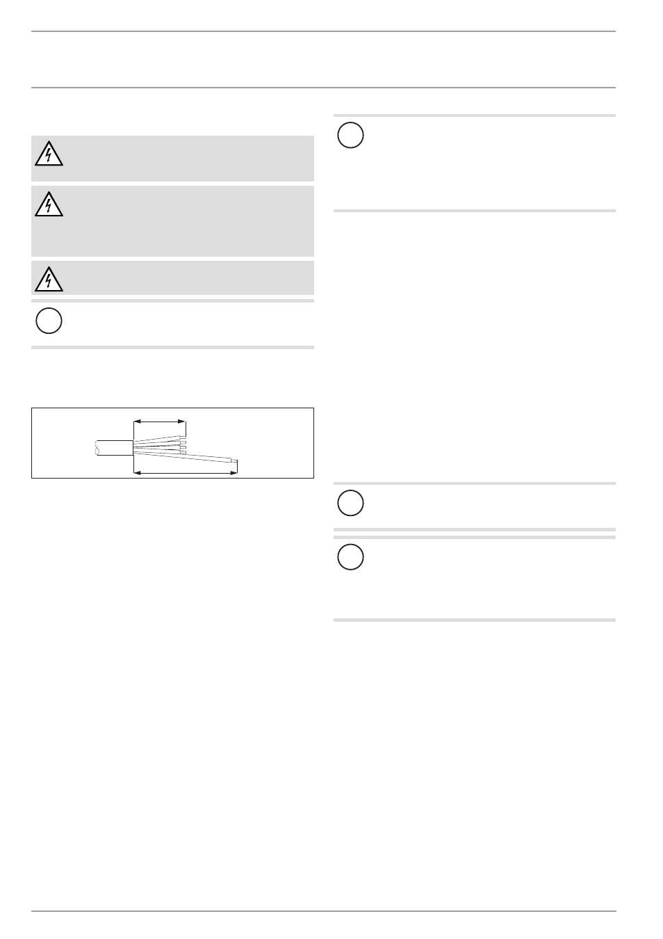
f
f Select a cable of the cross-sectional area suited to the load
of the appliance. Prepare the power cable, ensuring that the
earth conductor is longer than the other conductors.
f
f Feed the power cable through the cable entry into the control
panel.
f
f Connect the required load in accordance with the wiring
diagrams (see chapter "Specification / Wiring diagrams and
connections").
f
f Fit the control panel cover.
f
f If required, push the temperature selector back on.
f
f Appliance type with dual circuit operation: Use a ballpoint
pen to mark the selected connected load and voltage on the
type plate.
!
Material losses
Contactors for thermostats or high limit safety cut-outs
must be installed outside the control panel of the flanged
immersion heater. The contactors must be switched inde-
pendently of one another by the thermostats and the high
limit safety cut-out respectively (see chapter "Specifica-
tion / Wiring diagrams and connections").
If the appliance is operated with power-OFF control, you must
install the power-OFF contact between the contactors or upstream
of the contactor.
Required contactor breaking capacity:
Sizing in accordance with the connected load (see chapter
"Specification / Data table") for l
e
/ AC-1 / 70 °C (thermal con-
stant current with a resistive load at an ambient temperature of
up to 70 °C).
f
f Label the contactors according to their function.
f
f If required, mark any live components inside the control
panel that are supplied with power from outside.
f
f Once connected, check that the contactors are functioning
properly.
10. commissioning
10.1 commissioning
f
f Fill the system with water.
!
Material losses
Boiling dry destroys the thermostat, which must then
be replaced. The high limit safety cut-out must be reset.
!
Material losses
If an indirect coil is installed in the same cylinder, limit
the maximum temperature for this appliance to the maxi-
mum temperature for the flanged immersion heater. This
prevents the high limit safety cut-out of the flanged im-
mersion heater from responding.
appliance handover
f
f Explain the appliance function to users and familiarise them
with its operation.
f
f Make users aware of potential dangers.
f
f Hand over these instructions.
10.2 recommissioning
See chapter "Commissioning".