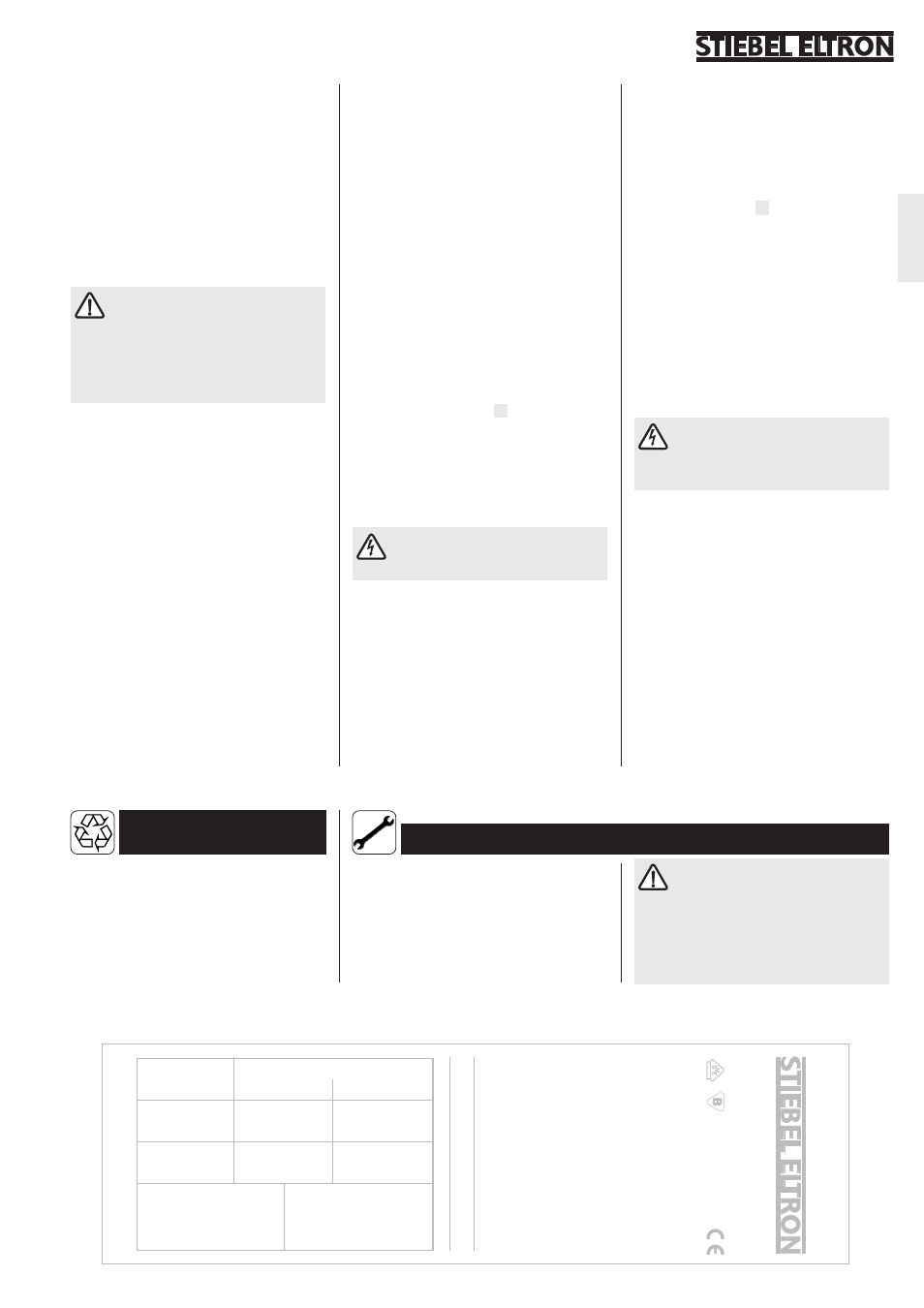
Guarantree, Environment and recycling, Affix the type label of the heated mat her e – STIEBEL ELTRON FTD с 06.01.2003 User Manual
Page 11: 4 installation, 5 first start-up, 6 handover
11
English
Heated floor mat
FT
. ...
acc
. DIN 44576
T
ype-No
.:
.. .
. .
.
Pr
od.-No
.:
. .
. .
Rated v
oltage:
230 V
Rated po
w
er
:
...
W
Width of mat:
.,.. m
Length:
.,.. m
Total resistance:
... Ohm
Rated limit temper
ature:
90 ºC
Alter
nating v
oltage sustaining capability 4000
V
Insulation resistance checke
d
M E A S U R E D D A T A
BEFORE
laying the mat
AFTER
laying the mat
Total resistance
(Ohm)
Insulation
resistance
(megaohms)
Room:
Company:
Date / Signature:
Name :
Please be
war
e back pa
ge
!
Prod.-No
. :
3. Environment and
recycling
For guarantees please refer to the respective
terms and conditions of supply for your
country.
Please help us to protect the environment by
disposing of the packaging in accordance with
the national regulations for waste processing.
The installation, electrical connection
and first operation of this appliance
should be carried out by a qualified installer.
The company does not accept liability for
failure of any goods supplied which are not
installed in accordance with the
manufacturer's instructions.
Affix the type label of the heated mat her
e!
4. Guarantree
This creates an additional built-up height
including the heated mat of 6 to 8 mm. Apply
the desired covering after drying.
In the case of a poorly insulated subfloor or
one which is at risk from cracking, a floor
insulation board should if possible be laid
between the subfloor and the heated mat,
for the purpose of insulating or uncoupling
the heated mat.
2.4 Installation
The type label attached to the heated
floor mats must be filled in, using the
appropriate information, and must be
affixed to these installation instructions.
In the case of FTD series heated floor
mats, all fitted labels are to be removed.
2.4.1 Positioning of the floor
temperature probe
Prior to laying the heated mat, the
temperature probe (6) of the floor
thermostat must be laid. Attention is to be
paid to the following in this process:
The floor temperature probe is to be:
– laid in 11 mm empty trunking centrally
between two parallel heating conductors.
The empty trunking is to be recessed into
the substructure flush with the surface, and
sealed at the end;
– laid at a location which is representative
for the room (e.g. centre of the room), so
that the floor temperature which is set at
the control unit can be adhered to.
If the probe is installed at an unfavourable
location, false temperature measurements
by the probe and associated defective
control actions can occur as a consequence
of the following circumstances:
•
heat build-up - caused by additional
covering of the probe zone, e.g. by
erecting a cupboard
•
covering the largest area of the floor, but
not in the probe zone
•
continual draught through an open
window
For this, the operating and installation
instructions for the thermostat are to be
noted.
2.4.2 Laying the mat
Lay out the heated floor mat(s). To make
work easier, it is recommended that the
heated mat(s) is/are fixed in position using
securing pegs (5, special accessories).
By separating the reinforced glass fabric, it is
possible to lay several heating paths, accord-
ing to requirements (see
D
). Thus, for
example, the PTC connectors can also be
laid closer to the mains supply point
(thermostat). Attention must be paid to
ensuring that the heating paths do not cross
and that the heating lines are not bent or
twisted.
It is only the fabric (2) which may be
separated, the heating lines (1) must
not be severed under any circumstances.
After laying and any fixing of the heated mats,
the two PTC connectors (4) are to be laid
to the connection box of the thermostat, for
example through trunking.
During and after laying, the heated mats are
to be stepped on only to the extent which is
absolutely necessary, to avoid mechanical
damage. If necessary, special measures are to
be taken in this regard, for example wearing
shoes with rubber soles and placing and
moving the requisite equipment (tools) on
suitable supports.
2.4.3 Electrical connection
The electrical connection of the heated floor
mat is to be carried out in accordance with
the connection plan (
C
) in these installation
instructions.
Before and after the electrical connection of
the heated mat(s), the insulation resistance,
the continuity of current, and the resistance
value are to be measured.
The maximum permissible current in the
case of parallel connection of several heating
mats amounts to 10 A.
It is absolutely imperative to note the rated
current of the thermostat!
The protective braiding of the PTC
connectors serves to earth the
heated mats and must be connected to the
earth terminals of the thermostat.
2.5 First start-up
On the occasion of the first start-up, the
floor heating is to be heated up briefly
several times, since cracks in the top covering
can otherwise arise.
2.6 Handover
Explain the functions of the heated mat and
the thermostat to the user. Make him or her
aware of the safety instructions, in particular.
Hand over the operating and installation
instructions to the user, as well as the type
label. This is held to be a guarantee
document and must be retained.