4 internal components – Asus P3-P5G31 User Manual
Page 16
1-6
Chapter 1: System introduction
1.4
Internal components
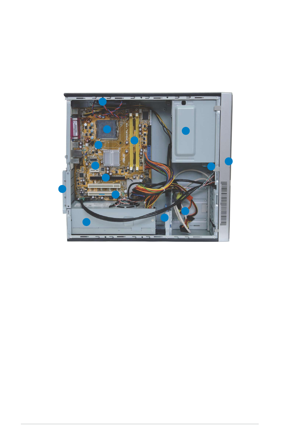
The illustration below is the internal view of the system when you remove the top
cover and the chassis support bracket. The installed components are labeled
for your reference. Proceed to Chapter 2 for instructions on installing additional
system components.
1. 5.25-inch empty optical drive bay
2. Front panel cover
3. Optical drive lock
4. Hard disk drive bays
5. Hard disk drive lock
6. Power supply unit
7. PCI slots
8. PCI Express x16 slot
9. PCI Express x1 slot
10. ASUS motherboard
11. Metal bracket lock
12. LGA775 socket
13. DIMM sockets
14. Chassis fan
1
3
7
5
8
2
6
4
11
9
12
13
10
14
See also other documents in the category Asus Computers:
- CG8565 (410 pages)
- CG8565 (246 pages)
- CS5111 (26 pages)
- CS5120 (1 page)
- ET1611PUK (38 pages)
- S2-P8H61E (80 pages)
- P2-PH1 (80 pages)
- P1-P5945G (80 pages)
- P2-P5945GCX (90 pages)
- CG8270 (218 pages)
- CG8270 (536 pages)
- CG8270 (72 pages)
- CG8270 (76 pages)
- CG8270 (534 pages)
- CG8270 (362 pages)
- P3-PH4 (80 pages)
- P2-M2A690G (80 pages)
- P2-M2A690G (8 pages)
- P4-P5N9300 (1 page)
- P4-P5N9300 (82 pages)
- P1-P5945GC (92 pages)
- P2-P5945GC (92 pages)
- P3-P5G33 (98 pages)
- T3-P5945GC (80 pages)
- T3-P5945GCX (80 pages)
- P2-M2A690G (94 pages)
- T3-PH1 (80 pages)
- T3-PH1 (82 pages)
- T5-P5G41E (82 pages)
- T5-P5G41E (76 pages)
- S1-AT5NM10E (68 pages)
- P6-P7H55E (67 pages)
- ES5000 (174 pages)
- T4-P5G43 (104 pages)
- T-P5G31 (92 pages)
- BT6130 (60 pages)
- BT6130 (54 pages)
- BT6130 (2 pages)
- CG8265 (350 pages)
- CG8265 (210 pages)
- CM1740 (330 pages)
- CM1740 (70 pages)
- CM1740 (198 pages)
- P6-M4A3000E (59 pages)