2 controller, 2 controller -3 – 3Com External PoE Power System PSE2500-A3 User Manual
Page 14
User Manual
Chapter 2
PSE2500-A3 External PoE
Power System
System Description
2-3
Figure 2-2 Front panel of the rectifier
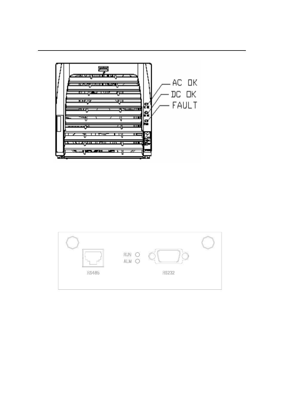
2.2 Controller
The system controller of PSE2500-A3 is installed within the
chassis. See figure 2-3.
Figure 2-3 Front panel of the controller
There are green LED (RUN) indicating operation status and red
LED (ALM) indicating the alarm on the front panel of the PSE2500-A3
controller. When the system has an alarm, such as input failure, input
over-voltage or under-voltage, output over-voltage or under-voltage,