Xantrex Technology SW5548 User Manual
Page 3
©2000 Xantrex Technology Inc.
The items listed in this addendum have changed to reflect product compliance with UL1741 First
Edition requirements. The changes only affect 120 VAC/60 Hz units using the SELL mode function
of the inverter/charger. The software revision has changed from 4.01 to 4.10.
Model Numbers Affected:
SW4024, SW4048 and SW5548 (120 VAC/60 Hz models only)
General Information:
The inverter software has been redesigned to meet UL1741 First Edition requirements which
incorporates IEEE929 recommended practices. These requirements have altered voltage and
frequency operating windows and have added a 5 minute grid connect timer delay before selling
power. In addition to user utility interactive changes, the inverter has been approved to meet the
rigorous non-islanding and harmonics analyses initiated by UL1741.
The SELL voltage window is now nonadjustable and locked at 106132 VAC range, indicated by
the inverters LINE TIE LED ON. Any voltage limits programmed in SET INPUT LOWER/UPPER
LIMIT VAC menu item (located under MENU HEADING 11) for input AC1, are displayed, but ignored
when the SELL mode is selected.
The SELL frequency window is nonadjustable and locked at 59.360.5 Hz anytime the inverter
is in SELL mode. This is indicated by the LINE TIE LED ON. For any voltage or frequency condition
outside these specified operating windows, the inverter will disconnect and attempt to reconnect to
the grid when proper voltage and frequency conditions are detected (after a 5 minute wait period
elapses). The inverter will reset the 5 minute timer each time an out-of-bounds condition is detected,
during periods when the AC1 light is blinking or ON.
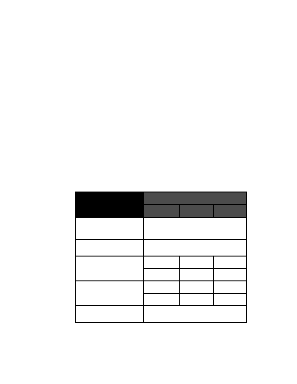
SOFTWARE REV 4.10
SW4024
SW4048
SW5548
AC Voltage Window
Fixed 106–132 VAC when SELL mode is
engaged (AC1 input only). Adjustable for all
other modes.
Frequency Window
59.3–60.5 Hz in SELL mode (AC1 input only),
54–66 Hz for all other modes.
SET MAX SELL AMPS
1–35
1–35
1–50
Default 33 A
Default 33 A
Default 46 A
SET MAX CHARGE AMPS
1–35
1–35
1–40
Default 30 A
Default 30 A
Default 35 A
TRACE ENGINEERING 3
Menu
REV 4.10
976-0013-D-001
1
ADDENDUM