York WORLD 50 HZ K3EU180A50 User Manual
Page 6
6
Unitary Products Group
035-12124-000 Rev. A (0501)I
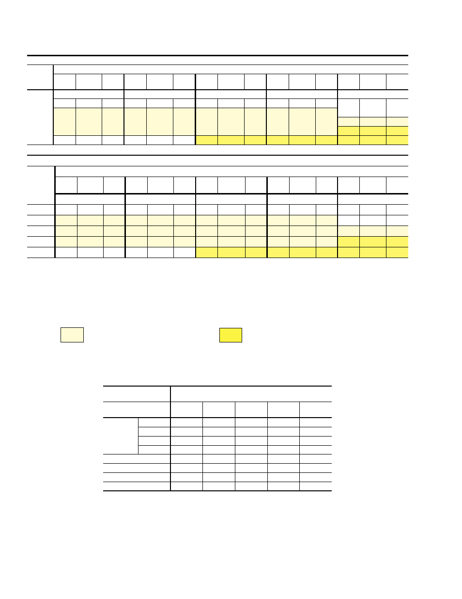
SUPPLY AIR BLOWER PERFORMANCE
1
- (CFM)
BLOWER
SPEED
RPM
AIRFLOW
ESP
2
(IWG)
OUTPUT
(BHP)
INPUT
(kW)
ESP
2
(IWG)
OUTPUT
(BHP)
INPUT
(KW)
ESP
2
(IWG)
OUTPUT
(BHP)
INPUT
(kW)
ESP
2
(IWG)
OUTPUT
(BHP)
INPUT
(kW)
ESP
2
(IWG)
OUTPUT
(BHP)
INPUT
(kW
4800 CFM
5400 CFM
6000 CFM
6600 CFM
7200 CFM
600
0.46
1.44
1.34
0.30
1.68
1.56
0.11
1.96
1.80
-
-
-
-
-
-
625
0.55
1.54
1.43
0.40
1.79
1.64
0.22
2.08
1.90
0.01
2.41
2.20
-
-
-
700
0.84
1.83
1.68
0.70
2.12
1.94
0.54
2.43
2.22
0.36
2.77
2.54
0.12
3.12
2.82
800
1.26
2.38
2.17
1.15
2.70
2.47
1.00
3.03
2.74
0.83
3.37
3.05
0.62
3.75
-
900
1.70
2.95
2.68
1.63
3.30
2.99
1.52
3.67
-
-
-
-
-
-
-
SUPPLY AIR BLOWER PERFORMANCE
1
- (m
3
/s)
BLOWER
SPEED
RPM
AIRFLOW
ESP
2
(Pa)
OUTPUT
(kW)
INPUT
(kW)
ESP
2
(Pa)
OUTPUT
(kW)
INPUT
(kW)
ESP
2
(Pa)
OUTPUT
(kW)
INPUT
(kW)
ESP
2
(Pa)
OUTPUT
(kW)
INPUT
(kW)
ESP
2
(Pa)
OUTPUT
(kW)
INPUT
(kW)
2.26 m
3
/s
2.55 m
3
/s
2.83 m
3
/s
3.11 m
3
/s
3.40 m
3
/s
600
114
1.07
1.34
74
1.25
1.56
27
1.46
1.80
-
-
-
-
-
-
625
136
1.15
1.43
99
1.33
1.64
55
1.55
1.90
3
1.08
2.20
-
-
-
700
208
1.36
1.68
174
1.58
1.94
134
1.81
2.22
89
2.06
2.54
30
2.32
2.82
800
312
1.77
2.17
285
2.01
2.47
248
2.26
2.74
206
2.51
3.05
154
2.79
-
900
422
2.20
2.68
404
2.46
2.99
311
2.73
-
-
-
-
-
-
-
1
Unit resistance is based on a wet evaporator coil and clean filters.
2
Available static pressure in IWG (Pa) to overcome the resistance of the duct system and any accessories added to the unit. Refer to Table 6 for the resistance of these
accessories and to Table 7 for additional motor and drive data
NOTE: Motors can be selected to operate into the service factor because they are located in the moving air stream, upstream of any heating device.
LEGEND:
TABLE 5 - BLOWER PERFORMANCE
RPM range for standard
factory-mounted drive components.
Exceeds the output limitation of the standard
factory-mounted blower motor.
TABLE 6 - ACCESSORY STATIC RESISTANCE (IWG)
ACCESSORY
EXTERNAL STATIC PRESSURE DROP RESISTANCE
IWG/pA
BLOWER CFM/m
3
/s
4800 /
2.26
5400 /
2.55
6000 /
2.83
6600 /
3.11
7200 /
3.40
Electric
Heat
10kW
0.04 / 10
0.05 / 12
0.06 / 15
0.08 / 20
0.10 / 25
16kW
0.07 / 18
0.09 / 21
0.11 / 27
0.14 / 35
0.17 / 42
26kW
0.13 / 32
0.16 / 40
0.20 / 50
0.24 / 60
0.29 / 72
36kW
0.20 / 50
0.24 / 60
0.29 / 72
0.35 / 87
0.42 / 106
Supply Air Plenum
0.03 / 8
0.04 / 10
0.05 / 12
0.06 / 15
0.07 / 18
Return Air Grille
0.04 / 10
0.05 / 12
0.06 / 15
0.07 / 18
0.08 / 20
Hot Water Coil
0.18 / 45
0.22 / 55
0.26 / 64
0.30 / 74
0.34 / 84
Steam Coil
0.15 / 37
0.18 / 45
0.22 / 55
0.26 / 64
0.30 / 74
* Add these pressures to the ESP values in the respective blower performance table.