Attaching clutch grips, Attaching handle panel, Attaching speed selector plate – Yard Machines 611 User Manual
Page 7: Attaching shift lever
7
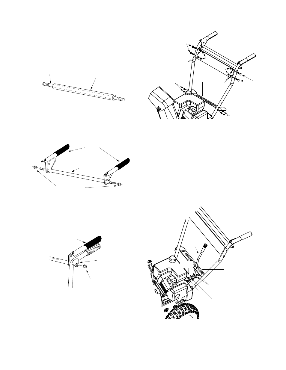
Attaching Clutch Grips
(Use Hardware Group B.)
•
Slide the pivot rod into the cover tube as shown in
Figure 3.
NOTE: In some models, the pivot rod and cover tube
may be pre-assembled.
Figure 3
•
Place the clutch grips in position on the rod as
shown in Figure 4. Thread hex nuts (D) onto each
end of the rod. Tighten nuts allowing the clutch
grips to move freely on the pivot rod. See Figure 4.
Figure 4
•
Insert clutch grip and rod assembly into handle
tabs. Clutch grips must sit on top of the handles.
Thread hex nuts (D) on each end to hold into
position. Do not tighten. See Figure 5.
Figure 5
Attaching Handle Panel
(Use Hardware C.)
•
Position the handle panel between handles. Insert
two carriage bolts (E) on each side and secure with
lock washers (C) and hex nuts (D). See Figure 6.
Figure 6
Attaching Speed Selector Plate
(Use Hardware D.)
•
Assemble the speed selector plate to the outside
of the handles as shown in Figure 6. Secure using
two self-tapping screws (F) on each side.
Attaching Shift Lever
•
Insert the shift lever through slot in the speed
selector plate. See Figure 7.
NOTE: The bend in the lever should be towards the
operator.
Figure 7
•
Secure shift lever to the shift lever spring using two
hex bolts (G) and hex lock nuts (H). Tighten both
Pivot Rod
Cover Tube
Clutch
Grips
Hex Nuts D
Pivot Rod
with Cover
Clutch Grip and
Rod Assembly
Handle
Tab
Hex Nut D
Carriage
Bolts E
Carriage
Bolts E
Hex
Nu
ts D
Lock
Washer C
Lock
Washer C
Speed
Plate
Selector
Self-Tapping
Screws F
Self-Tapping
Screws F
Hex Lock Nuts H
Hex
Bolt G
Hex
Bolt G
Shift Lever
Spring
Shift
Lever
Speed Selector
Plate