Ac panel – Xantrex Technology 1200 User Manual
Page 21
XPower Plus Features
2–4
AC Panel
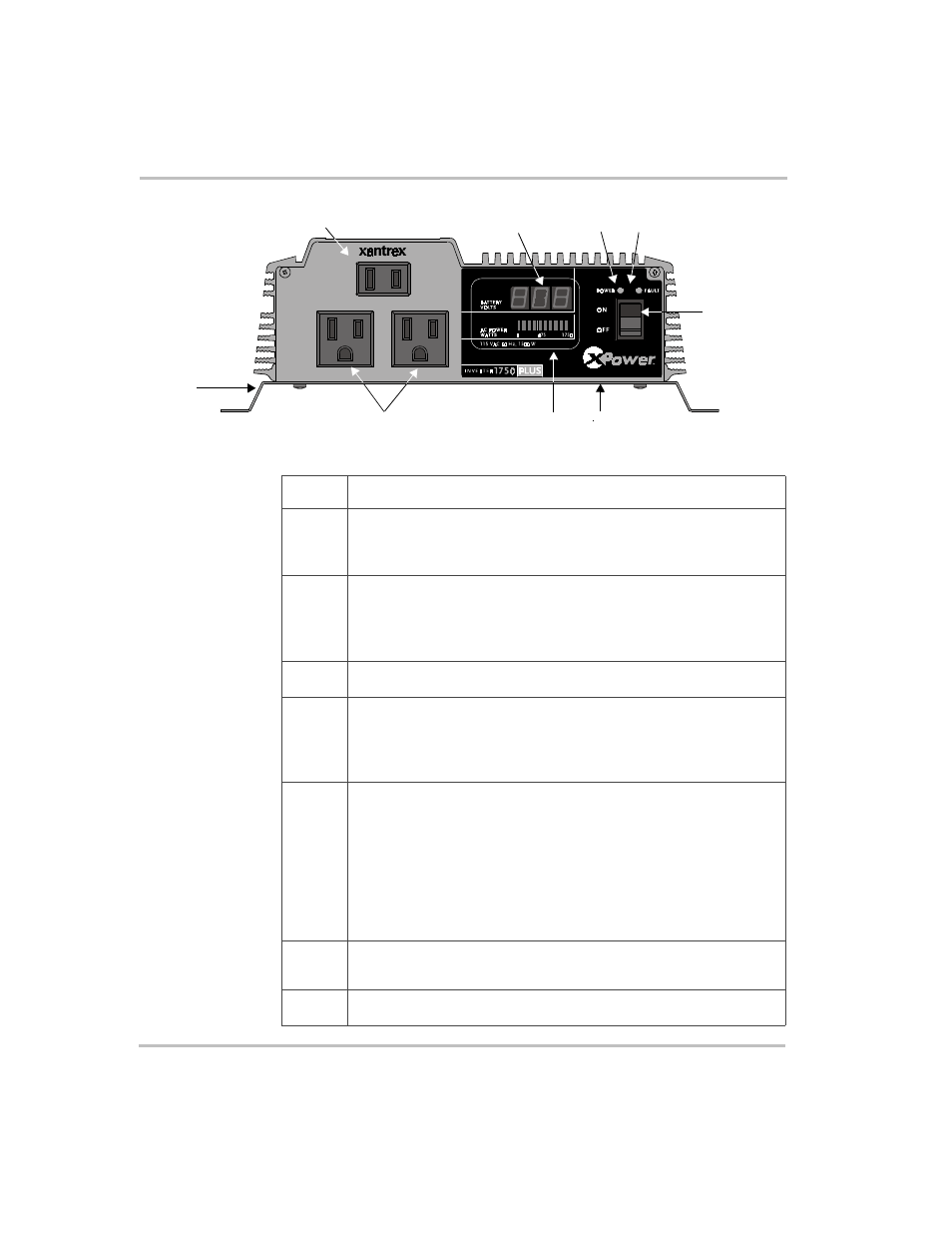
Figure 2-1 AC Panel (XPower 1750 Plus shown)
④
④
④
④
⑥⑥⑥⑥
⑤
⑤
⑤
⑤
⑦
⑦
⑦
⑦
⑧
⑧
⑧
⑧
⑨
⑨
⑨
⑨
①
①
①
①
③
③
③
③
②
②
②
②
Feature Description
➀
➀
➀
➀
On/Off Switch
turns the inverter’s control circuit on and off. This
switch is not a power disconnect switch. Disconnect AC and DC
power before working on any circuits connected to the inverter.
➁③
➁③
➁③
➁③
②
②
②
② Fault light is a red light indicating the inverter has shut down due
to low or high battery voltage, unit overload, or overtemperature.
③
③
③
③ Power light is a green light indicating the On/Off Switch is on and
AC voltage is present at the inverter’s AC outlets.
④
④
④
④
INPUT VOLTAGE DISPLAY
indicates battery voltage.
⑤⑥
⑤⑥
⑤⑥
⑤⑥
AC Outlets: ⑤
⑤
⑤
⑤ 2-Prong and ⑥ ⑥ ⑥ ⑥ 3-Prong XPower 1200 Plus delivers
a combined total of 1000 watts of continuous AC power across three
outlets. XPower 1750 Plus delivers a combined total of 1500 watts of
continuous AC power across three outlets.
⑦
⑦
⑦
⑦
OUTPUT POWER INDICATOR
•
The indicator should be in the green area for continuous
operation.
•
If the indicator is in the yellow area, the inverter will operate for
several minutes and then shut down.
•
If the indicator is in the red area, the inverter has reached the
maximum allowable power and is close to the output power
shutdown limit.
⑧
⑧
⑧
⑧
Remote Switch Jack (not shown) is on the bottom of the inverter,
and it is the connection point for the optional Remote On/Off Switch.
⑨
⑨
⑨
⑨
Mounting Flanges allow you to mount the inverter permanently.