Set up – Zenoah BRUSHCUTTERS BK4310FL-S User Manual
Page 10
10
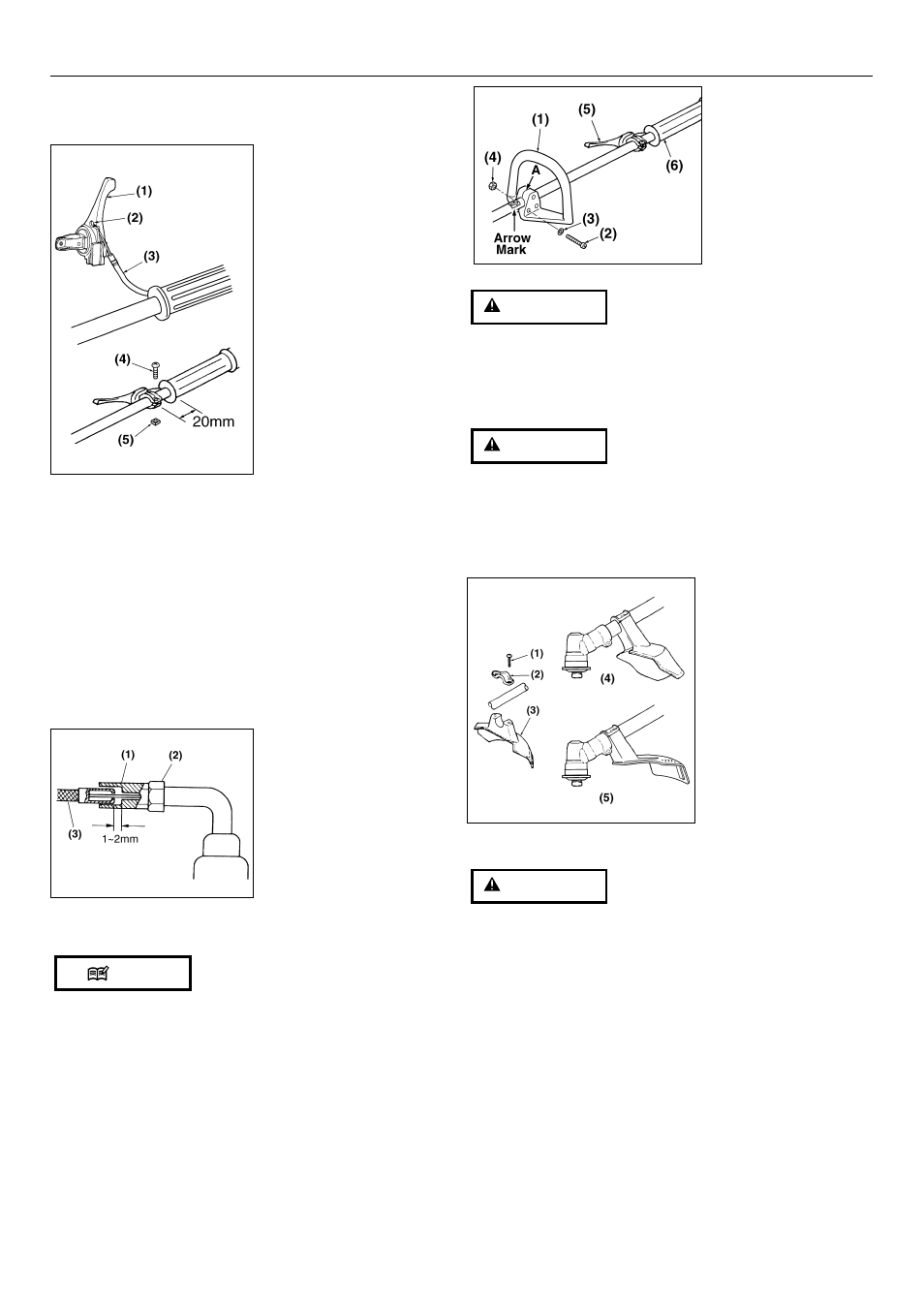
2. Attach the lever as shown in the picture and screw it
securely. (SE6)
(1) Throttle lever
(2) Hole
(3) Throttle cable
(4) Screw
(5) Nut
■ ADJUSTING THROTTLE CABLE
• Proper play of the throttle cable is 1–2mm. Place the
throttle lever to the lowest speed position (i.e. fully
released status). Pull the throttle cable lightly with
fingers to check its play. Readjust the position of
cable adjuster if the play is too large or too small. To
readjust, slacken a lock nut. Turn the cable adjuster
clockwise to increase the play, or counterclockwise to
decrease the play. Lock the cable adjuster with the
lock nut after readjustment. (SE7)
(1) Cable adjuster
(2) Lock nut
(3) Throttle cable
■ ATTACHING THE HANDLE
The loop handle should be located between the arrow
mark and the throttle lever.
• Attach the loop handle as shown in the
accompanying diagram. Note that it is recommended
that you attach the handle so that the handle is
located some 30–40cm away from the front end of
the right-hand grip. (SE8)
NOTE
SE6
5. Set up
SE7
(1) Loop handle
(2) Screw
(3) Washer
(4) Nut
(5) Throttle lever
(6) Right hand grip
Stop tightening the screws when the gap A
becomes zero.
■ ATTACHING THE DEBRIS GUARD
Never use the machine without the debris guard.
• Attach the guard to the clamp on the outer pipe just
touching the gearcase. Fix it with 2 bolts. (SE9)
(1) Bolt (M5x25)
(2) Clamp
(3) Debris guard
(4) Place to be
attached for blade
use
(5) Place to be
attached for line
head
■ BLADE
• Do not install or remove the blade while the
engine is in operation.
• Use ZENOAH’s genuine replacement blades and
metal fixtures when installing the blade.
• When installing or removing the blade, fix the
machine securely, and wear robust gloves.
• The blade turns counterclockwise (viewed from
the gear case). When using an inside-out blade,
check the direction of the blade before installing
it. In particular, if you install a chip saw in the
wrong direction, the chips might break and
scatter.
1. Loosen the bolt remove holder A and holder B from
the gear case. (SE10)
WARNING
WARNING
WARNING
SE9
SE8