Gas piping – Weil-McLain LGB-5 User Manual
Page 3
LGB
LGB
LGB
LGB
LGB-4
-4
-4
-4
-4 & 5
5
5
5
5
•
Control Supplement
•
UCS
•
Propane
3
Part Number 550-141-919/0304
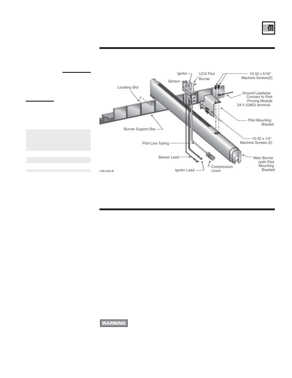
Figure 1
Pilot burner
assembly
Table 1
Pilot and
flame sensor
locations
1. Contact gas supplier to size pipes, tanks and regulator.
a. Inlet gas pressure to manual main shut-off gas valve minimum 11" W.C., maximum
13" W.C.
b. If pressure to gas valve exceeds 13" W.C., install 100% lock-up gas pressure regulator
upstream of hand valve.
2. Remove knockout disc from jacket panel side to which gas supply will be piped.
3. Follow good piping practices.
4. Pipe joint compound (pipe dope) must be resistant to corrosive action of liquefied petroleum
gases. Apply sparingly only to male threads of pipe joints.
5. Install drip leg at inlet of gas connection to boiler. Where local code/utility requires, extend
drip leg to floor.
6. Install ground joint union when required for servicing.
7. Support piping by hangers, not by boiler or its accessories.
8. Purge all air from supply piping.
9. Before operating boiler, check boiler and its gas connections for leaks.
Boiler
model
Electronic
pilot
burner *
Standing
pilot
burner *
Propane
carton
LGB-4
4
2
4 and 5
LGB-5
5
2
4 and 5
* Burner position, counting from left to right
III
Gas piping
Do not check for gas leaks with an open flame - use bubble test. Failure to
use bubble test or check for leaks can cause severe personal injury, death or
substantial property damage.
a. Close manual main shut-off valve during any pressure testing greater than 13" W.C.
b. Disconnect boiler and gas valve from gas supply piping during any pressure test
greater than 13" W.C.
10. In Canada - manual main shut-off valve must be identified by installer.