Step 4 : installing the autolatch, Step 3 : continued, Fig. 8 – Wayne-Dalton 8000 User Manual
Page 4: Fig. 2, Fig. 1
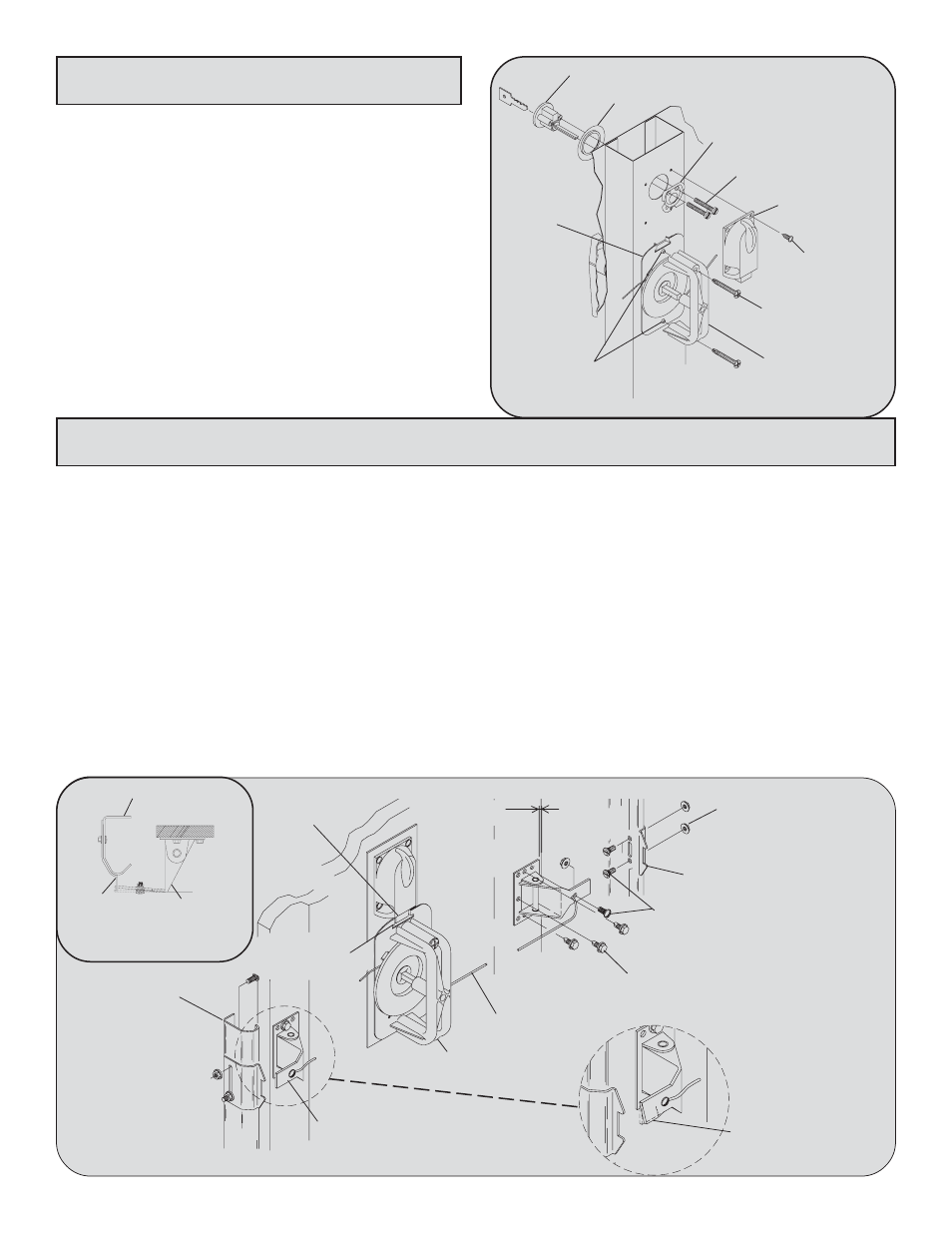
Step 4 : Installing The Autolatch
4
Place the lock plate over the 1-1/4” diameter center stile
hole and fasten with (2) #12 pan head screws into the
rim cylinder. In addition, align the night latch slide with
the notch in the top of the release disk. Fasten the night
latch to the center stile with (4) #8 x 1/2” pan head
screws.
NOTE: Follow the Main Installation Instruction
Manual to install the door sections and vertical track
before you install the remainder of the lock parts.
After the sections and track are installed, continue
with Step 4.
Step 3 : Continued
Locate the autolatch striker plates over the pre-punched holes in the vertical track nearest the center of the lock
section (as shown). Fasten the striker plates to the vertical track using (2) 1/4-20 x 9/16” track bolts and flanged
hex nuts. Align the autolatch flippers such that the arm will engage the striker plates. Position the autolatch flipper
1/8” from the edge of the section and secure it to the section with (3) 1/4 -20 x 11/16” self drilling screws (wood
doors will use 1/4-14 x 1” lag screws). Bend the bottom edge of the Autolatch flipper arm away from the door
slightly for smoother operation (On 9900 Series doors, bend the autolatch flipper toward the striker plate
until it is able to engage (see Fig. 2). Feed one end of the lock cable through the slotted hole of an Autolatch
flipper and secure with (1) 1/4-20 x 9/16” track bolt. Pull the cable taut, but not enough to lift the flipper out of the
striker plate. While holding taut, feed the lock cable through the slotted hole of the remaining Autolatch flipper,
secure with (1) 1/4-20 x 9/16” track bolt and flanged hex nut. NOTE: Ensure that the bolt is through the front
of the flippers and the nut is on the back of the flippers with cable going through the front of the flippers.
Operate the lock several times to make sure the Autolatch flippers clear the striker plates when the handle is turned
and the flippers engage the striker plates when the handle is released. Adjust the cables if necessary. Trim off the
excess cable with wire cutters after the lock is operating satisfactorily.
USE PLIERS TO BEND
LOCK ARM SLIGHTLY
1/4-20 X 11/16”
SELF DRILLING SCREWS
1/8” OFFSET FROM
EDGE OF DOOR
1/4-20 FLANGED
HEX NUTS
1/4-20 X 9/16”
TRACK BOLT
LOCK CABLE
STRIKER PLATES
Fig. 8
RIM CYLINDER
TRIM RING
LOCK PLATE
(2) #12 PAN
HEAD SCREWS
NIGHT LATCH
(4) #8 X 1/2”
PAN HEAD
SCREWS
(2) 1/4-20 X 1-3/4”
SELF TAPPING
SCREWS
RELEASE
DISK
EXTRUDED HOLES
IN RELEASE DISK
INSIDE HANDLE
“SLIDE” OF
NIGHT LATCH
“NOTCH” OF
RELEASE DISK
INSIDE
HANDLE
VERTICAL
TRACK
AUTOLATCH
FLIPPERS
Fig. 2
AUTOLATCH
FLIPPER
TRACK
STRIKER
PLATE
Fig. 1