General specifi cations, Warning, Professional service required – Weil-McLain UO-3 CV User Manual
Page 6: Notice special requirements, Table 2 – air tube combination (atc) codes
6104BAFG R0
6
Page 5
General Specifi cations
Please read and understand the manual supplied with
this equipment. This equipment must be installed, ad-
justed and put into operation only by a qualifi ed individu-
al or service agency that is:
Licensed or certifi ed to install and provide tech-
nical service to oil heating systems.
Experienced with all applicable codes, standards
and ordinances.
Responsible for the correct installation and com-
mission of this equipment.
Skilled in the adjustment of oil burners using
combustion test instruments.
The installation must strictly comply with all applicable
codes, authorities having jurisdiction and the latest revi-
sion of the National Fire Protection Association Standard
for the installation of Oil-burning Equipment, NFPA 31
(or CSA-B139 and CSA-B140 in Canada).
Regulation by these authorities take precedence over
the general instructions provided in this installation
y
y
y
y
Incorrect installation, adjustment,
and use of this burner could result
in severe personal injury, death, or
substantial property damage from
WARNING
!
Professional Service
Required
fi re, carbon monoxide poisoning, soot or explo-
sion.
Notice Special Requirements
THE INSTALLATION OF A BURNER SHALL BE
IN ACCORDANCE WITH THE REGULATIONS
OF AUTHORITIES HAVING JURISDICTION.
For recommended installation practices in the
U.S. refer to the latest edition of NFPA 31. (CSA-
B139 and CSA-B140 in Canada.
Concealed damage — If you discover damage to
the burner or controls during unpacking, notify the
carrier at once and fi le the appropriate claim.
When contacting Beckett for service information
— Please record the burner serial number (and
have available when calling or writing). You will
fi nd the serial number on the silver label located
on the left rear of the burner. Refer to Figure 1.
y
y
y
y
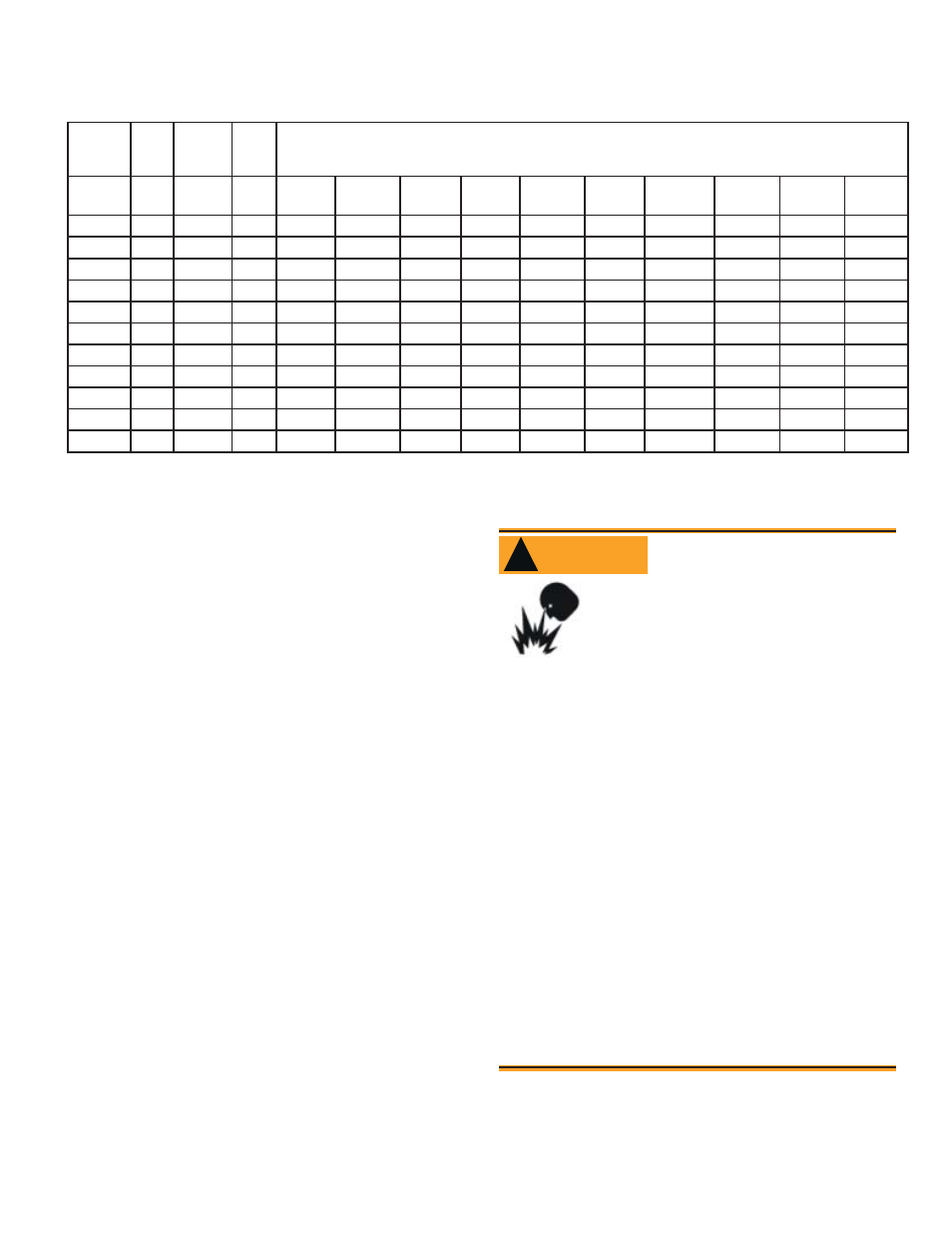
Table 2 – Air Tube Combination (ATC) codes
Firing
Rate
(gph)
Head
Static
plate
size
Ven-
turi
ATC Codes for usable air tube lengths
(‘A’ in inches; See Figure 3.)
(min-
max)
(inches)
4-1/2
5
5-3/8
6-5/8
7
7-1/4
9
10-1/2
13
16
0.50-0.75
F0
3-3/8U
None
AF44XR
-
AF53XR
AF65XR
-
AF72XR
AF90XR
AF104XR
AF130XR
A160XR
0.75-1.25
F3
2-3/4U
None
AF44XN
-
AF53XN
AF65XN
-
AF72XN
AF90XN
AF104XN
AF130XN
AF160XN
0.85-1.35
F4
2-3/4U
None
AF44WH
-
AF53WH
AF65WH
-
AF72WH
AF90WH
AF104WH
AF130WH
AF160WH
0.85-1.65
F6
2-3/4U
None
AF44YB
-
AF53YB
AF65YB
-
AF72YB
AF90YB
AF104YB
AF130YB
AF160YB
1.10-2.00
F12
2-3/4U
None
AF44XO
-
AF53XO
AF65XO
-
AF72XO
AF90XO
AF104XO
AF130XO
AF160XO
1.65-2.50
F22
2-3/4U
None
AF44XP
-
AF53XP
AF56XP
-
AF72XP
AF90XP
AF104XP
AF130XP
AF160XP
2.50-3.00
F31
None
None
AF44XS
-
AF53XS
AF65XS
-
AF72XS
AF90XS
AF104XS
AF130XS
AF160XS
0.50-1.10
L1
3-3/8U
8hole
-
AFG50MB
-
-
AFG70MB
-
AFG90MB
-
-
-
0.50-1.00
L2
2-3/4U
8hole
AFG50MP
-
-
AFG70MP
-
AFG90MP
-
-
-
0.75-2.75
V1
2-3/4U
8hole
-
AFG50MD
-
-
AFG70MD
-
AFG90MD
-
-
-
0.40-0.75
F0
3-1/2U
None
AF44WG
-
AF53WG
AF65WG
-
AF72WG
AF90WG
AF104WG
AF130WG
A160WG