Waterpik Technologies LG User Manual
Page 19
Model LG Pool and Spa Heater
Page 17
6.1 Main Power
The Lite2 model LG heater does not require an
external source of electrical power to operate. The
power for the gas valve and safety circuit are gener-
ated by a thermopile. The thermopile generates a
millivolt signal when heated by the pilot flame. Figure
17 shows the internal electrical wiring diagram and
schematic of the heater.
6.2 Bonding
CAUTION
This heater must be connected to a bonding
grid with a solid copper wire not smaller in
diameter than 8 ga.
ATTENTION
L’appareil de chauffage doit être connecté à
une grille de mise à la terre par un fil de cuivre
d’un diamètre de calibre minimal 8.
The National Electrical Code and most other
codes require that all metallic components of a pool
structure, including reinforcing steel, metal fittings
and above ground equipment be bonded together with
a solid copper conductor not smaller than a number 8
wire. The heater, along with pumps and other such
equipment must be connected to this bonding grid. A
special labeled bonding lug is provided on the right side
of the heater to accommodate this requirement.
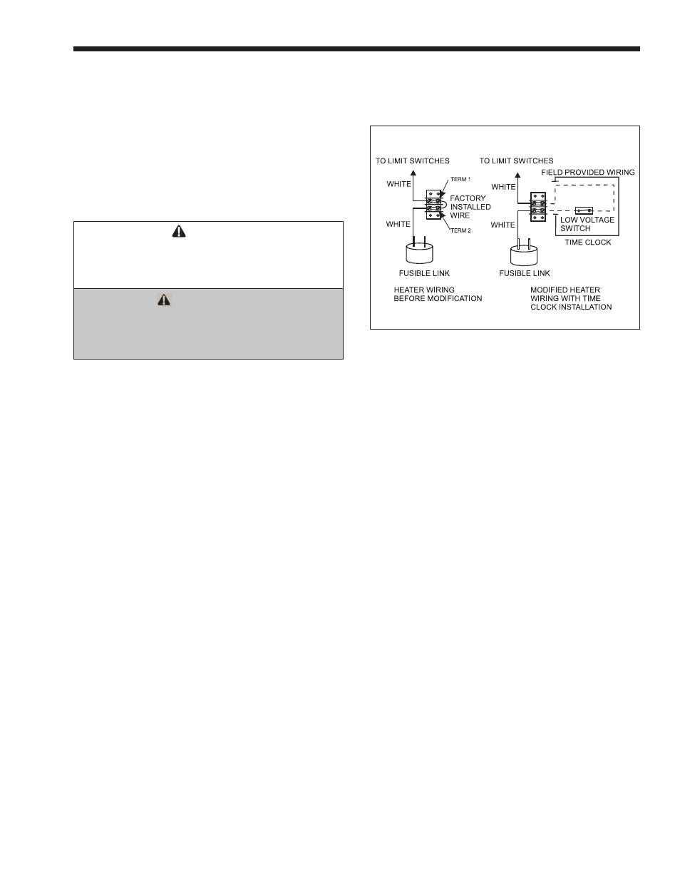
6.3 Auxiliary Time Clock Wiring
If you install a time clock to control the filter
pump operation, it is recommended that the time clock
have its own low voltage (Fireman’s) switch to turn
off the heater before turning off the pump. The switch
should shut off the heater about 15 minutes before the
filter pump shuts off. This will allow for a more
efficient operation by removing any residual heat
contained in the heat exchanger back to the pool.
To install a time clock auxiliary switch into the
heater wires (see Figure 16):
1.
Remove heater door.
2.
Remove the factory installed wire between
terminals 1 and 2 on the terminal strip (see
Figure 16).
3.
Connect the wires from the time clock auxiliary
switch to the two terminals. Use American Wire
Gage (AWG) No. 14 gauge stranded copper wire
with a temperature rating of 221°F (105°C) or
greater.
Figure 16. Time Clock Wiring.
The length of the wire between the heater and
the time clock should not exceed 10-15 feet (4.57 m).
The contact points of the time clock switch should be
silver, or a low resistance alloy.
SECTION 7.
Operating Instructions
7.1 Normal Operation
The Lite2 model LG heaters are capable of
automatic operation based on a call for heat at a preset
temperature. The heater has an internal safety system
which allows operation in a variety of conditions and
prevents operation when certain adverse conditions are
encountered.
When the heater's pilot is lit and the pilot genera-
tor is providing a millivolt signal to the safety circuit,
water is flowing through the heater, and the tempera-
ture of the water entering the heater is below the
temperature control setting, an operating cycle is
initiated by the automatic control. The temperature
control circuit is closed, activating the gas valve and
the gas valve is opened. Gas flows through the burn-
ers, is mixed with air in the combustion chamber, and
is ignited by the pilot. Operation will continue until
the temperature of the water entering the heater
reaches the temperature control setting.
If ignition is unsuccessful, or if the flame fails
during normal operation, the temperature control
circuit opens and shuts off the gas valve.