Checking the system, Typical 3-zone gas fired system, Typical multi-zone gas or oil fired system – White Rodgers DAMPER MOTOR 2061 User Manual
Page 4
4
2
2
4
1
3
2
2
4
1
3
2
2
4
1
3
S81-0125
Transformer
Line
G
H
2061 Damper Motors
White-Rodgers Damper Motor Thermostats (Two-Wire)
High Limit
Pilot
26A00 Series
Low Voltage
Diaphragm Gas Valve
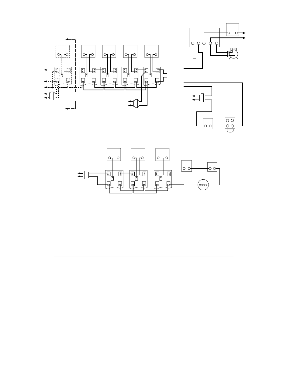
Typical 3-Zone Gas Fired System
Transformer supplies
power for low voltage
gas valve as well as
damper motors.
2
T
T
1
2
3
2
2
4
1
3
2
2
4
1
3
2
2
4
1
3
2
2
4
1
3
2
2
4
1
3
Additional
Zones
Transformer
LINE
G
H
Line
G
H
LINE
G
H
2
1
3
Burner
Motor
Line
G
H
2061 Damper Motors
White-Rodgers Damper Motor Thermostats (Two-Wire)
x
x
x
x
x
x
3
1
4
High Limit
HIGH LIMIT
Low Voltage
Constant Ignition
Oil Burner Control
LOW VOLTAGE
SILENT KNIGHT
GAS VALVE
PLUG-IN PILOT
S81-0126
TRANSFORMER
S81-0125
Transformer
For
Gas
For
Oil
Typical Multi-Zone Gas or Oil Fired System
CHECKING THE SYSTEM
Turn on the electricity. If gas fired, be sure pilot is lit. Then
check each zone separately as follows:
1. Turn thermostat to highest setting. Damper vane for
that zone will open and furnace burner will come on as
auxiliary circuit is made on damper motor.
2. Turn thermostat to lowest setting. Damper vane for
that zone will close and furnace burner will shut off as
auxiliary circuit is broken on damper motor.