Wiring diagram, Thermostat quick reference, The thermostat buttons and switches – White Rodgers 1F89-0211 User Manual
Page 3: The display
3
WIRING DIAGRAM
L
R
C
24 VAC
120 VAC
Hot
SYSTEM
MONITOR
SWITCH
Neutral
THERMOSTAT
SYSTEM
G
W2
Figure 2. Typical wiring diagram for single transformer systems
TRANSFORMER
(Class II Current Limited)
Changeover
Relay*
Y
O/B
Compressor
Contactor
Changeover Relay is energized in COOL when O/B switch is in the “O” position
Changeover Relay is energized in HEAT when O/B switch is in the “B” position
The 24 volt neutral connection to terminal C on the thermostat is not required if you
replace the batteries once a year with fresh “AA” alkaline batteries.
Aux/Emergency
Heat Relay
(Stage 2)
Fan
Relay
**
*
**
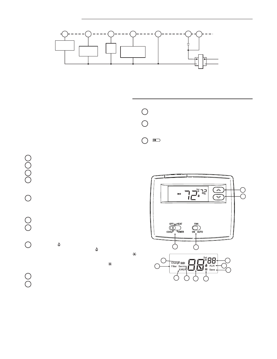
11 “EMER” is displayed flashing when the system switch is
in EMER position.
12 “Change Filter” is displayed when the system has run
for the programmed filter time period as a reminder to
change or clean your air filter.
13 “
” indicates when batteries are low and should be
replaced.
2
1
3
4
5
6
7
8
9
10
11
13
12
THERMOSTAT QUICK REFERENCE
Before you begin programming your thermostat, you should be
familiar with its features and with the display and the location
and operation of the thermostat buttons and switches (see fig.
3). Your thermostat consists of two parts: the thermostat cover
and the base. To remove the cover, pull it straight out from the
base. To replace the cover, line up the cover with the base and
press until the cover snaps onto the base.
The Thermostat Buttons and Switches
1 Raises temperature setting.
2 Lowers temperature setting.
3 SYSTEM switch (COOL, OFF, HEAT, EMER).
4 FAN switch (ON, AUTO).
The Display
5 Indicates setpoint temperature. This is blank when system
switch is in the OFF position. Setpoint temperature is
displayed (flashing) if the thermostat is in lockout mode to
prevent the compressor from cycling too quickly.
6 “AUX” indicates auxiliary stage is operating.
7 “Save” indicates the Cool Savings feature is enabled in
the configuration menu.
“Save” (flashing) indicates Cool
Savings feature is active.
8 Flame icon ( ) is displayed when the SYSTEM switch is
in the HEAT position.
Flame icon ( ) is displayed flashing
when thermostat is calling for heat.
Snowflake icon (
) is displayed (non-flashing) when the SYSTEM switch is
in the COOL position.
Snowflake icon ( ) is displayed
(flashing) if the thermostat is calling for cool.
9 Displays current temperature.
10 “Service” indicates a diagnostic fault in the heating/
cooling system. It does not indicate a fault in the
thermostat.
Figure 3. Thermostat display, buttons and switches