Installation, Series 2) — control supplement, Gas piping diagram - lgb (series 2) iri gas train – Weil-McLain FLAME GUARDIAN WMBC-1A User Manual
Page 4: Continued
Part Number 550-141-807/0298
4
LGB
(Series 2) — Control Supplement
16
13
15
17
18
18
14
12
11
10
9
7
6
5
4
3
2
1
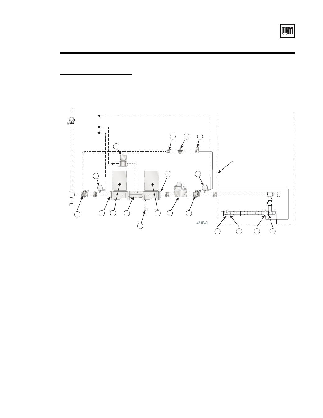
Boiler Jacket
V
ent to Outside
Atmosphere
Drip L
eg
Service V
alve
9
Second motorized gas valve w/ on/off actuator
1
Manual main shut-off gas valve
2
Low gas pressure switch
3
Pilot manual shut-off valve
4
Motorized gas valve w/ on/off actuator
5
Pilot gas pressure regulator
6
Normally open solenoid vent valve
7
Pilot solenoid gas valve
8
Test cock
10 Manual leak checking gas valve
11 Regulating diaphragm gas valve (two stage)
12 High gas pressure switch
13 Main flame sensor
14 Main burner with main flame sensor bracket
15 Pilot burner
16 Main burner with pilot burner bracket
18 Pipe flanges
17 Adapter, for N. O. vent valve
GAS PIPING DIAGRAM - LGB (Series 2)
IRI Gas Train
8
I
Installation
– continued
Figure 4
IRI gas train schematic
- BMC (32 pages)
- GOLD CGt SERIES (3 pages)
- SERIES 2 LGB-8 (11 pages)
- LGB-23 (12 pages)
- ULTRA 105 (60 pages)
- ULTRA 310 (1 page)
- -105 (28 pages)
- 550-141-830/1202 (12 pages)
- GV Series 4 (8 pages)
- GAS CONVERSION KIT GV-4 510-811-605 (2 pages)
- Ultra Series 2 (2 pages)
- ULTRA 155 (2 pages)
- GOLD CGI-4E (68 pages)
- SB0002 (2 pages)
- EGH-105 (36 pages)
- AQUA PLUS GL-E223-ADOC 0311 (44 pages)
- GOLD CGS 550-110-260/0508 (64 pages)
- BCP-8S (28 pages)
- LGB-4 (8 pages)
- HE II Boiler (5 pages)
- LGB-6 (12 pages)
- C-1013 (24 pages)
- CGs (24 pages)
- P-SGO (4 pages)
- GOLD CGS-4E (64 pages)
- Oil-Fired Water Boiler (4 pages)
- LGB (24 pages)
- Gold CGa (68 pages)
- GV90+ (108 pages)
- GOLD CGs (16 pages)
- PLUS LINE PLUS-E017-A/1206 (68 pages)
- WGO (12 pages)
- PFG (24 pages)
- PEG-30 THRU -65 (24 pages)
- LGB-20 (12 pages)
- Boiler (32 pages)
- 382-200-300 (2 pages)
- Ultra Electric Water Heater (12 pages)
- GOLD CGI SERIES 2 (68 pages)
- 88 (40 pages)
- PFG Series (3 pages)
- EGH-85 (16 pages)
- Gold GV 3 Series (16 pages)
- SERIES 7 PFG (16 pages)