White Rodgers 1F58 User Manual
1f58, White-rodgers, Installation instructions description
WHITE-RODGERS DIVISION
EMERSON ELECTRIC CO.
9797 REAVIS ROAD
ST. LOUIS, MISSOURI 63123-5398
PART NO. 37-5391A
9505
FAILURE TO READ AND FOLLOW ALL INSTRUCTIONS CAREFULLY
BEFORE INSTALLING OR OPERATING THIS CONTROL COULD CAUSE
PERSONAL INJURY AND/OR PROPERTY DAMAGE.
INSTALLATION INSTRUCTIONS
DESCRIPTION
Printed in U.S.A.
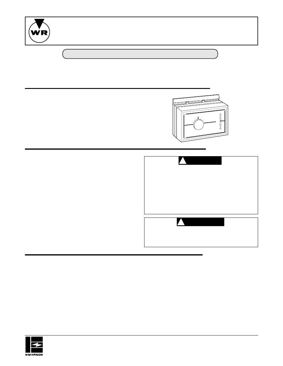
1F58
Low Voltage Multi-Stage Heat PumpThermostat
WHITE-RODGERS
This thermostat and subbase combination is designed to
control a heat pump system where automatic changeover
is not required. However, manual changeover of the
reversing valve can be controlled by the wiring selection
on the subbase and the switching of the SYSTEM switch
to COOL or HEAT (see fig. 2).
PRECAUTIONS
CAUTION
!
WARNING
!
SPECIFICATIONS
ELECTRICAL DATA
Switch Rating:
24 VAC
Stage 1 heat – 0 to 1.2 amp
Stage 2 heat – 0.15 to 1.2 amp
Cooling – 0 to 1.5 amp
Switch Action:
Stage 1 heat & cool – SPDT
Stage 2 heat – SPST (sealed mercury contacts)
Anticipator Rating:
Stage 1 heat – 24 VAC, fixed
Stage 2 heat – 0.15 to 1.2 amp, adjustable
Cooling – 24 VAC, fixed
Fan Circuit: See Fig. 2 – FAN CAUTION
THERMAL DATA
Temperature Range: 50
°
F to 90
°
F (10
°
C to 32
°
C)
Rated Differential: Stage 1 heat – 1.5
°
F
Stage 2 heat – 1
°
F
Cooling – 1.5
°
F
If in doubt about whether your wiring is millivolt, line, or low
voltage, have it inspected by a qualified heating and air
conditioning contractor, electrician, or someone familiar
with basic electricity and wiring.
Do not exceed the specification ratings.
All wiring must conform to local and national electrical
codes and ordinances.
This control is a precision instrument, and should be
handled carefully. Rough handling or distorting compo-
nents could cause the control to malfunction.
To prevent electrical shock and/or equipment
damage, disconnect electric power to system, at
main fuse or circuit breaker box, until installation
is complete.
Do not short out terminals on gas valve or primary
control to test. Short or incorrect wiring will burn
out heat anticipator and could cause personal
injury and/or property damage.
Do not use on circuits exceeding 30 volts. Higher
voltage will damage control and could cause
shock or fire hazard.
50
90
80
70
60
50
SYSTEM
COOL
OFF
HEAT EMER.
FAN
AUTO
ON
60
70
80
90
Operator: Save these instructions for future use!