Waterford Appliances LEPRECHAUN 90 O.S.A User Manual
Page 2
LEPRECHAUN 90 O.S.A.
WOODBURNING STOVE
INSTALLATION & OPERATING
INSTRUCTIONS
GENERAL
When installing, operating and maintaining your
Leprechaun 90 O.S.A. Stove respect basic stan-
dards of fire safety. Read these instructions careful-
ly before commencing the installation. Failure to do
so may result in damage to persons and property.
Consult
your
local
Municipal
Office,
Fire
Department, and your insurance representative to
determine what regulations are in force. Save these
instructions for future reference.
PRE-INSTALLATION ASSEMBLY
Step 1:
After removing the stove from its packing, open the
firedoor door and remove the contents from the fire
box.
Step 2:
Lay the stove on its side and fit the 4 legs (item 1)
with the
1/4
” (6.4mm) hex sets screws provided,
tighten screws. Stand the stove upright, taking care
not to strain the leg bolts.
Step 3:
Install the Hot Plate (item 15) into the large opening
of the hob (item 13). Do not remove the Hot Plate
when the stove is lighting.
THIS STOVE MAY BE CONNECTED TO EITHER A
TOP OR A REAR VENT.
REAR FLUE EXIT
Fit back sealing plate (Part no. 17) over the top flue
aperture in the hob (Part no. 13). Fit the flue spigot
to part no 11 where part no. 17 was, making sure
that part no. 17 and part no. 14 are well secured on
a bed of fire cement.
TOP FLUE EXIT
Fit part no. 14 over top
flue aperture in the hob
(Part No. 13) make sure
that part no. 14 is well
secured on a bed of fire
cement.
ASSEMBLY OF OPTIONAL
CHIMNEY PIPE SHIELD
HEAT SHIELD
ASSEMBLY
Top Exit:
Fit the head shield as
follows:
Screw the 4” 100mm x
1/4” 6mm tie bolts to the
back panel (item 11). Fit
the four 1” 25mm spacers
(item 31) over the tie bolts.
Fit the inner heat shield (item 28) with the blanking
plate on to the four tie bolts. Now fit the other four 1”
25mm spacers over the tie bolts and fit the outer heat
shield (item 30) complete with heat shield blanking
plate. Tighten the whole assembly together using the
four 1/4” 6mm nuts and washers provided.
2
The complete installation must be done in accor-
dance with current Standards and Local Codes. It
should be noted that the requirements and these
publications may be superseded during the life of
this manual.
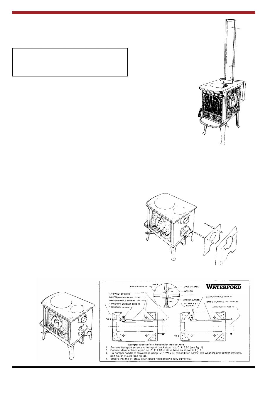
DAMPER HANDLE ASSEMBLY
Leprechaun 90 O.S.A.
Spacer
Heat Shield
Spacer
Fionn 90 OSA