Initial adjustment, Caution – Wells COUNTER TOP GAS HOTPLATE H-2412G User Manual
Page 9
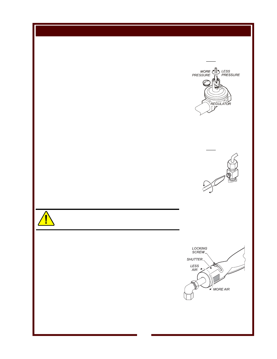
INITIAL ADJUSTMENT
SET GAS PRESSURE:
Turn the gas shut-off valve OFF.
A gas pressure test tap is provided on the gas supply manifold.
Remove both burner control knobs and the front panel. Remove
plug in gas pressure test tap and attach a manometer.
Turn the shut-off valve ON. Light the pilot light and turn both gas
control valves to HI. Depress both actuator heads.
Remove the cap from the pressure regulator. Turn the adjusting
screw clockwise to increase pressure; counter-clockwise to
decrease pressure. Adjust the gas pressure regulator for:
5” water column (natural gas); or, 10” water column (propane).
When finished, replace cap on regulator, turn shut-off valve OFF,
remove manometer and reinstall plug in tap. Reassemble
hotplate, turn shut-off valve back ON and relight pilot light.
SET PILOT FLAMES:
Remove left side (rear burner) control knob by pulling straight
off. Pilot flame adjustment screw is located to the right side of the
burner
control
valve.
Using a small, flat-blade screwdriver, turn the screw clockwise to
decrease the flame size, or counter-clockwise to increase the
flame
size.
Burner should light quickly and completely when burner actuator
is depressed. Adjust pilot flame to 1/4” high. Drafty conditions
may require a higher flame to allow pilot flame to remain lit.
Reinstall the control knob.
ADJUST BURNER FLAME:
CAUTION:
BURN HAZARD
Wear heat protective gloves. Avoid contact with flame.
Remove grate, drip tray and actuator heads. Turn both burner
control knobs full on. Adjust one burner at a time.
Loosen locking screw on a burner assembly shutter. Using a
metal implement such as a long-handle ladle, press the actuator
to light burner.
Turn shutter to admit more or less air as required. Adjust air
shutter until flame is mostly blue in color.
Tighten locking screw. Reassemble hotplate when finished.
IMPORTANT:
Pressure adjustment must
be performed by a qualified
technician only.
Fig. 3 Gas Pressure Adjustment
IMPORTANT:
Flame adjustment must be
performed by a qualified
technician only.
Fig. 4 Pilot Flame Adjustment
NOTE:
The right knob controls the front
burner; the left knob controls
the rear burner.
Fig. 5 Burner Flame Adjustment
7
LESS
FLAME
MORE
FLAME
M
228 036916
Op
M
H-2412 In
sta
n
t-
On Dual
Pilo
t
Gas
Hotplate