Burner specifications and settings, Continued), Table 2 – Weil-McLain RLS User Manual
Page 3: Table 3, Burner data — #2 fuel oil/natural gas — modulating, Gas control components and sizes
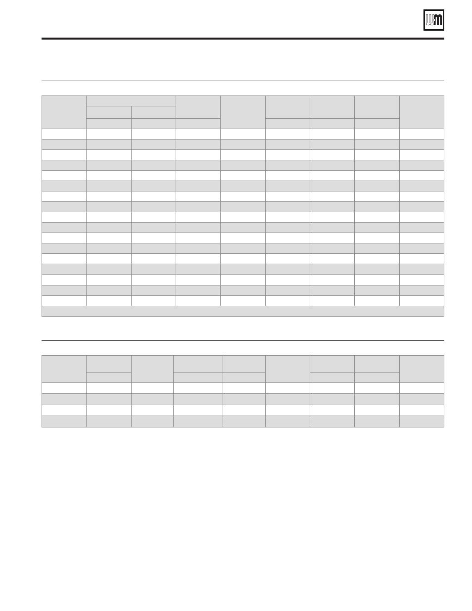
Burner Specification & Data sheet — Riello Gas/Oil Burners
3
Part No. 550-142-023/0508
Burner data — #2 Fuel oil/Natural gas — Modulating
Table 2
Boiler Model
Number
Burner Input
Positive
Pressure in
Firebox
Standard Burner
Model Designation
Standard
Combustion
Control
Standard Control
System
Burner Motor
3400 RPM
Standard Motor
Voltage
No. 2 Oil
Gas
GPH
MBH
Inches W.C
Note 16
Gas/Oil
H.P.
488R
6.90
996
0.89
RLS28
LFL 1.335
LHL/LHL
1/2
120/60/1
488
7.00
1010
1.00
RLS28
LFL 1.335
LHL/LHL
1/2
120/60/1
588
9.40
1357
0.84
RLS38
LFL 1.335
LHL/LHL
1/2
120/60/1
688
11.80
1703
0.72
RLS50
LFL 1.335
LHL/LHL
3/4
3 phase*
788
14.20
2049
0.65
RLS50
LFL 1.335
LHL/LHL
3/4
3 phase*
888
16.60
2396
0.85
RLS70
LFL 1.335
MOD/LHL
1 1/2
3 phase*
988R
17.20
2482
0.80
RLS70
LFL 1.335
MOD/LHL
1 1/2
3 phase*
988
18.80
2713
0.80
RLS70
LFL 1.335
MOD/LHL
1 1/2
3 phase*
1088R
20.00
2887
0.82
RLS70
LFL 1.335
MOD/LHL
1 1/2
3 phase*
1088
21.50
3103
0.82
RLS100
LFL 1.335
MOD/LHL
2 1/2
3 phase*
1188
23.50
3392
0.82
RLS100
LFL 1.335
MOD/LHL
2 1/2
3 phase*
1288
26.00
3753
0.81
RLS100
LFL 1.335
MOD/LHL
2 1/2
3 phase*
1388
28.50
4113
0.89
RLS100
LFL 1.335
MOD/LHL
2 1/2
3 phase*
1488
31.00
4474
0.86
RLS130
LFL 1.335
MOD/LHL
3
3 phase*
1588
33.00
4763
0.86
RLS130
LFL 1.335
MOD/LHL
3
3 phase*
1688R
34.50
4979
0.863
RLS130
LFL 1.335
MOD/LHL
3
3 phase*
1688
35.50
5124
0.83
RLS130
LFL 1.335
MOD/LHL
3
3 phase*
*208/60/3, 240/60/3, 480/60/3, 575/60/3 burner motor voltage must be specified
Gas control components and sizes
Table 3
Boiler
Model
Number
Manual
Hand Valve
Low Gas
Pressure Switch
Gas
Pressure Regulator
Operating
Gas Valve
Operating Gas
Valve (with Proof Of
Closure)
Safety
Gas Valve
Manual
Checking Gas Valve
High Gas
Pressure Switch
Inches
Inches
Inches
Inches
Inches
488R – 588
1 1/2
Standard
1 1/2
1 1/2
Optional
1 1/2
1 1/2
Standard
688 – 1088
2
Standard
2
2
Optional
2
2
Standard
1188 – 1288
2 1/2
Standard
2 1/2
2 1/2
Optional
2 1/2
2 1/2
Standard
1388 – 1688
3
Standard
3
3
Optional
3
3
Standard
Burner specifications and settings
(continued)
Notes for Table 1, Table 2 and Table 3
(continued)
be driven to both low fire and high fire positions, prevent start up if
pre-ignition interlocks are open and has low fire start proven circuit.
In the event pre-ignition interlock circuit or running interlock circuit
does not “prove”, system will lock out on safety. Ultra violet sensitive
electronic flame detector is standard.
Other flame safeguards available upon request.
17.
Control circuit transformer is available as an option.
18.
Airflow safety switch is standard for all gas and combination gas/light
19.
oil units.
Burners will be completely assembled and wired (except gas train) and
20.
factory test-fired.
Burners listed by Underwriters Laboratories, Inc., state of Connecticut, Fire
21.
Marshal state of Massachusetts, city of New York MEA, and others.
Special controls can be provided to meet other code requirements not listed.
22.
Consult your local Weil-McLain distributor/agent or sales office.
Electric gas pilot will be furnished as standard equipment on all combina-
23.
tion gas/light oil units.
Direct spark ignition is available as an option for combination gas/light oil
24.
units. Consult your local Weil-McLain distributor/agent or sales office.